Read all of the instructions before proceeding.
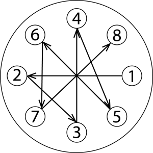
Refer to Kadant Johnson assembly drawing for part identification and to drawing A37640 for torque specifications. For easy identification, parts used in individual steps are often accompanied with their position in the assembly drawing [e.g. gasket (8B)]. Tighten all fasteners in a star pattern. Certified drawings are available upon request. Dimensions are for reference only and subject to change.

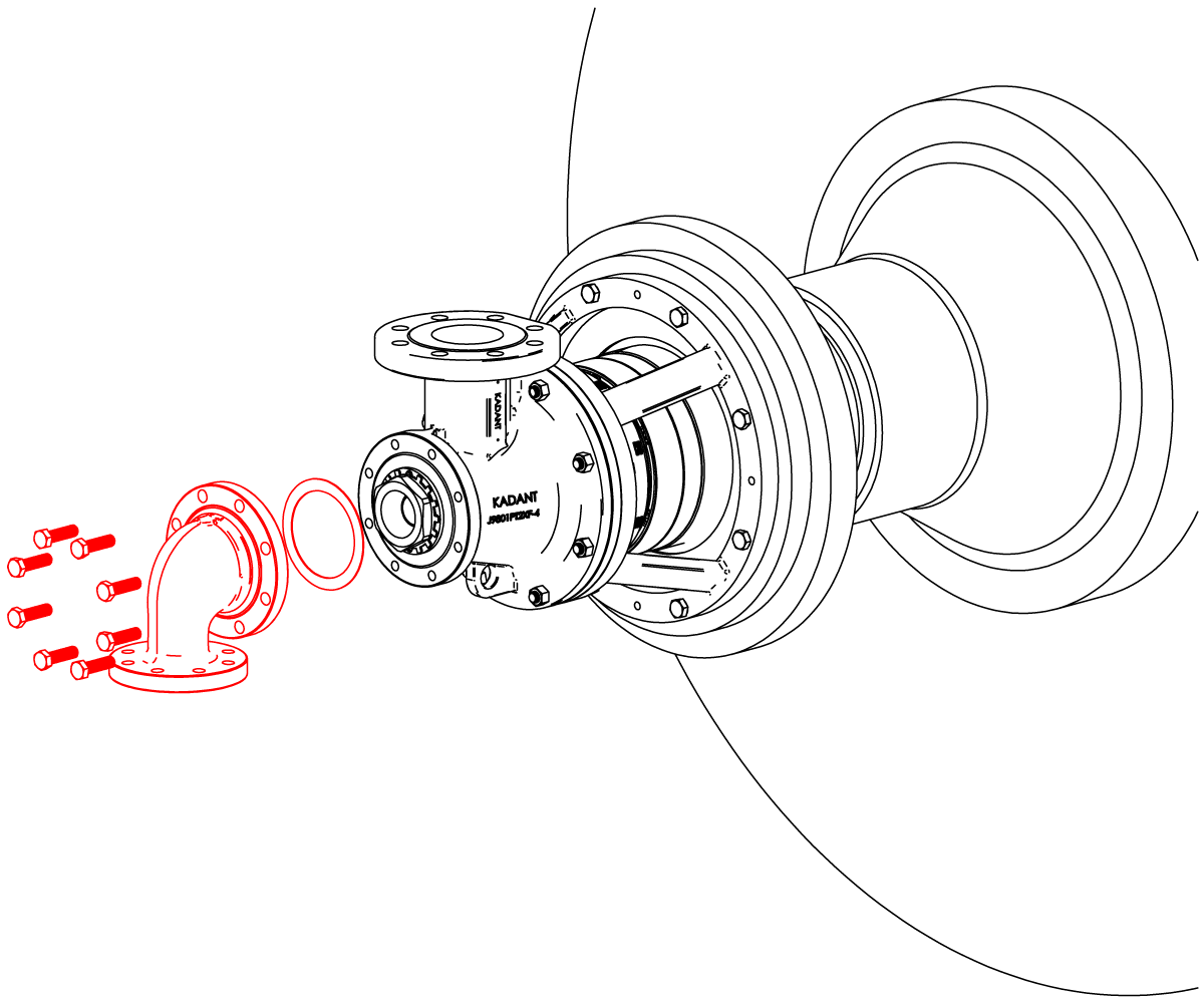
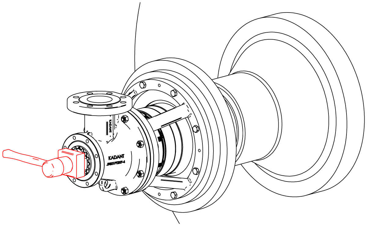
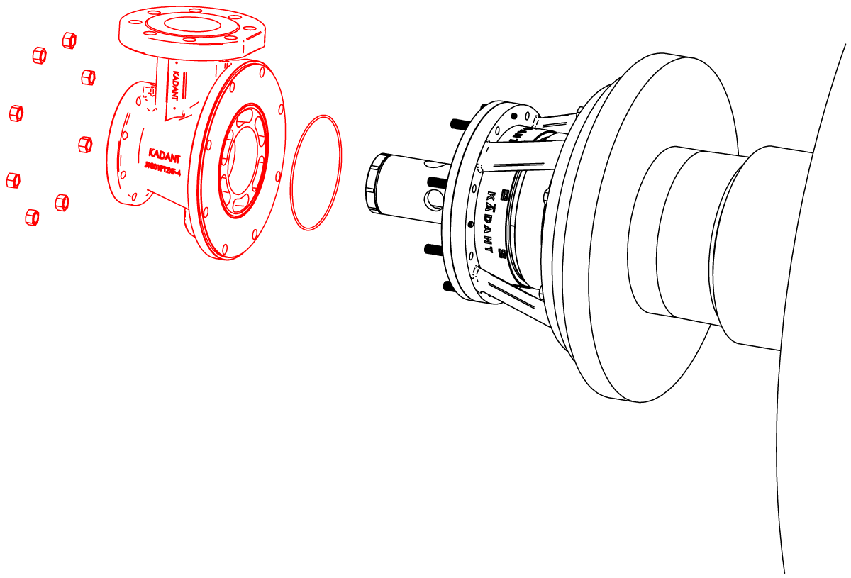
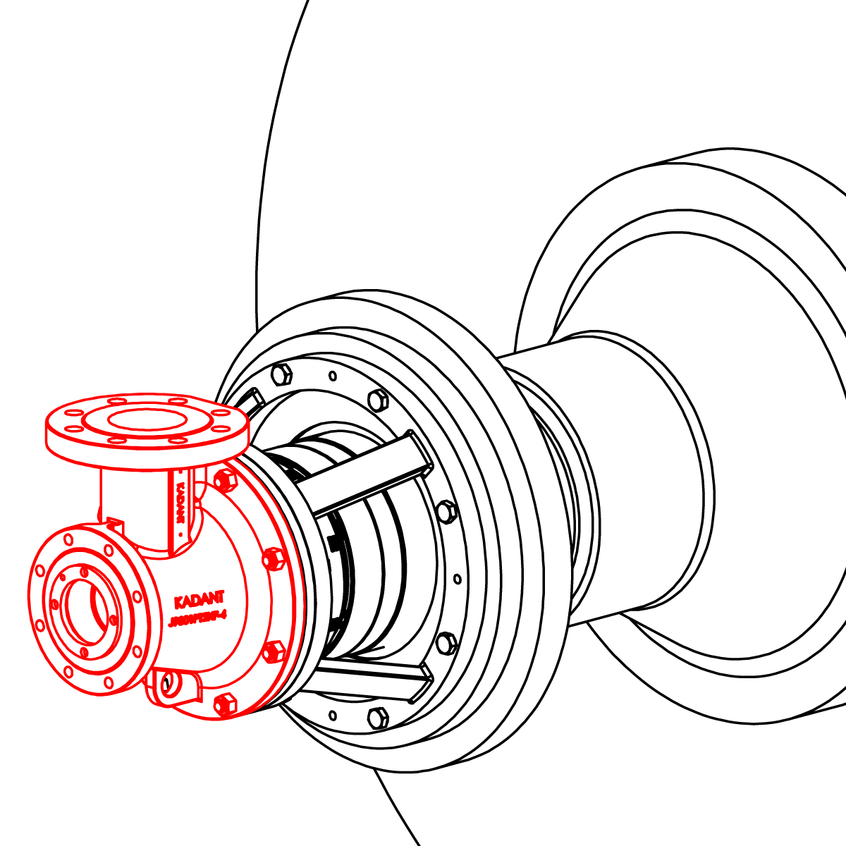
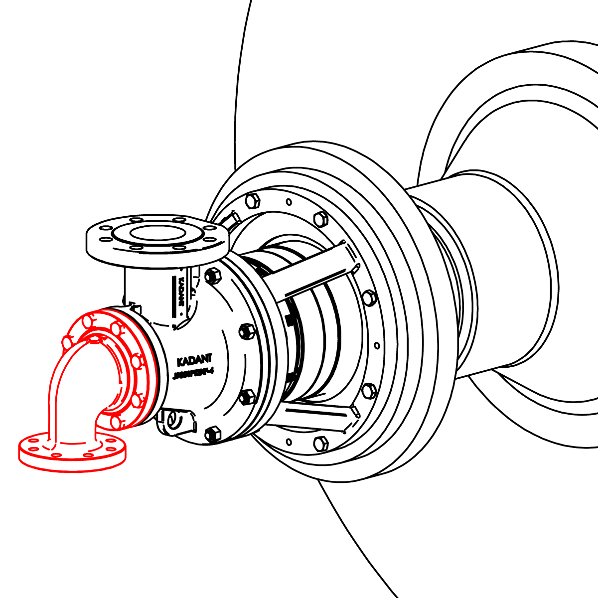
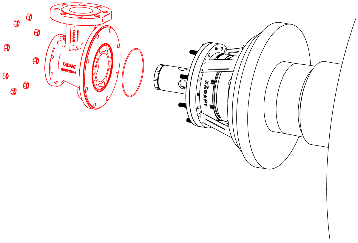
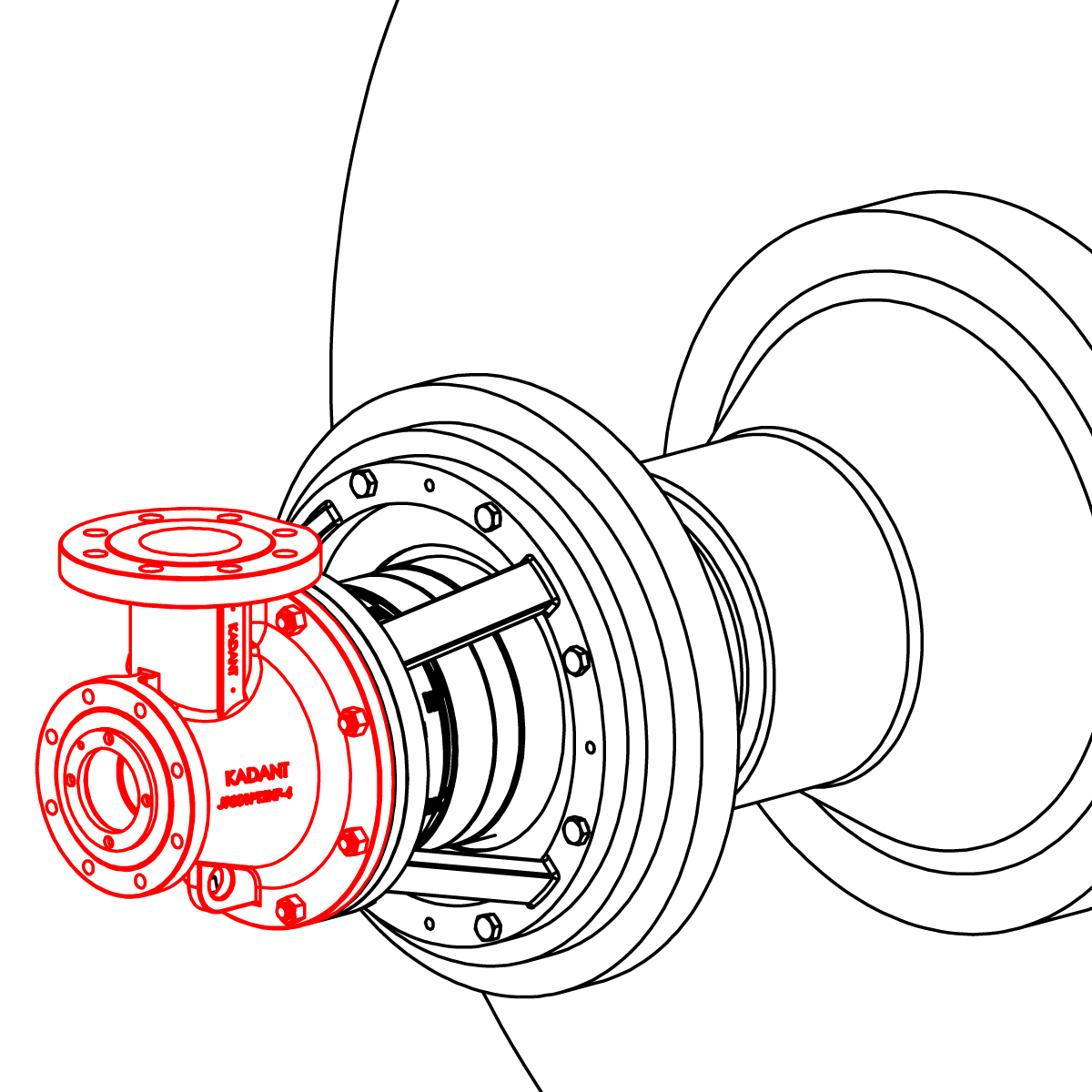
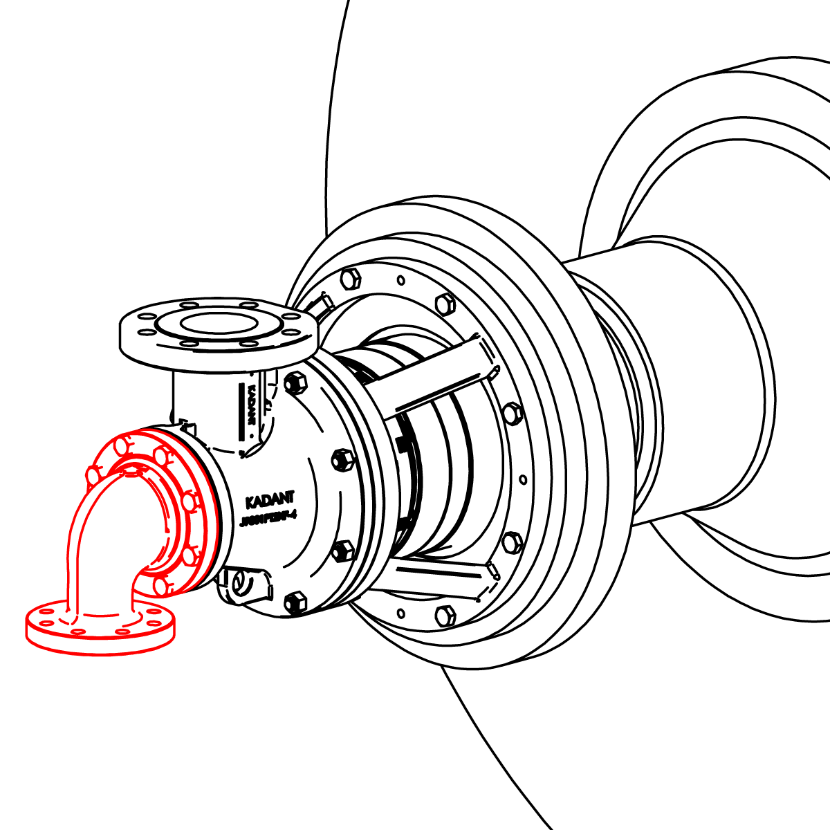
Disconnect piping. Remove the head and set aside.

Bend tabs back from support tube nut.
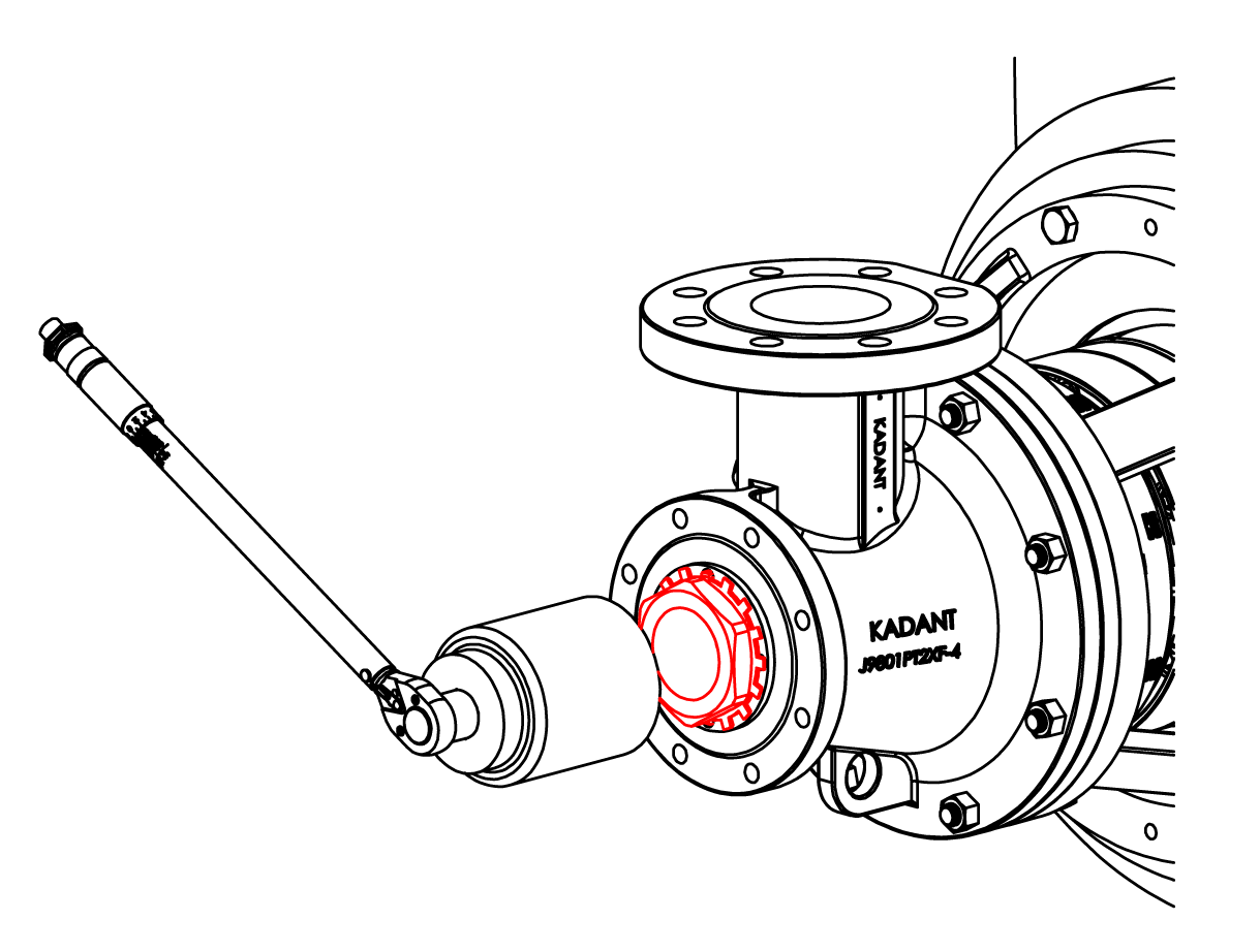
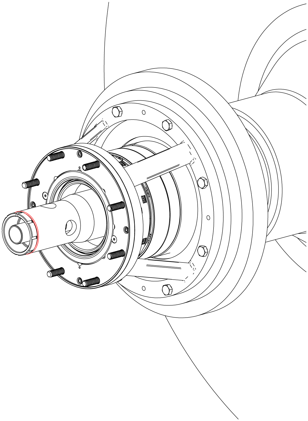
Unthread the support tube nut aproximently 1/4" (6.4 mm). Place a block of wood over the hollow bolt and strike it with a hammer. This will break the tapered seal inside of the rotary joint. Remove the support tube nut and set aside for reuse.
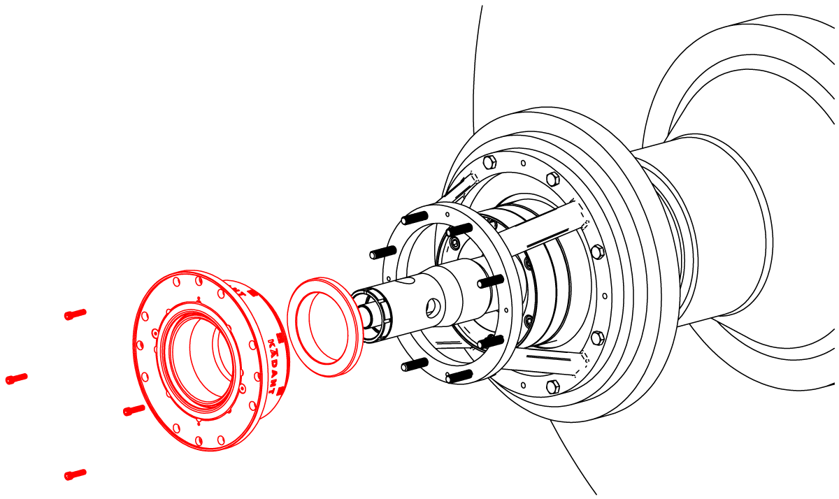
Important: Note the location of the indexing slot on the end of the support tube.
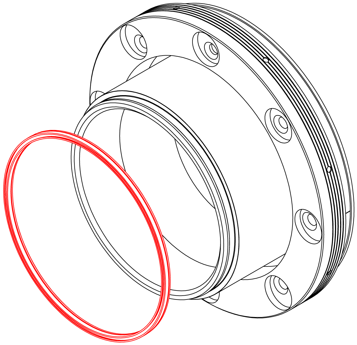
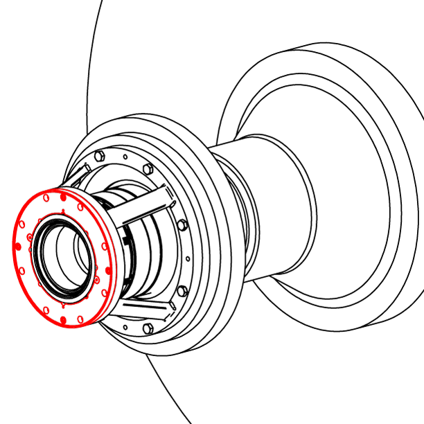
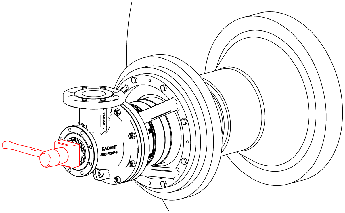
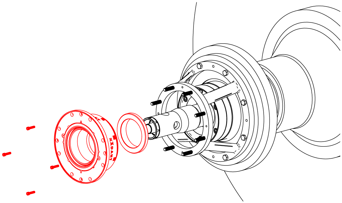
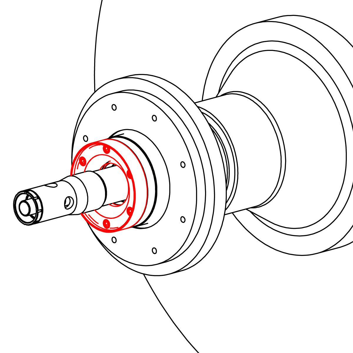
Remove the body and set aside with the O-ring side up. Remove and discard the O-ring (26).
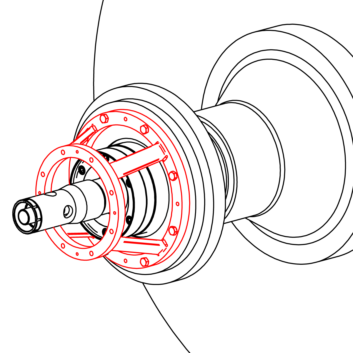
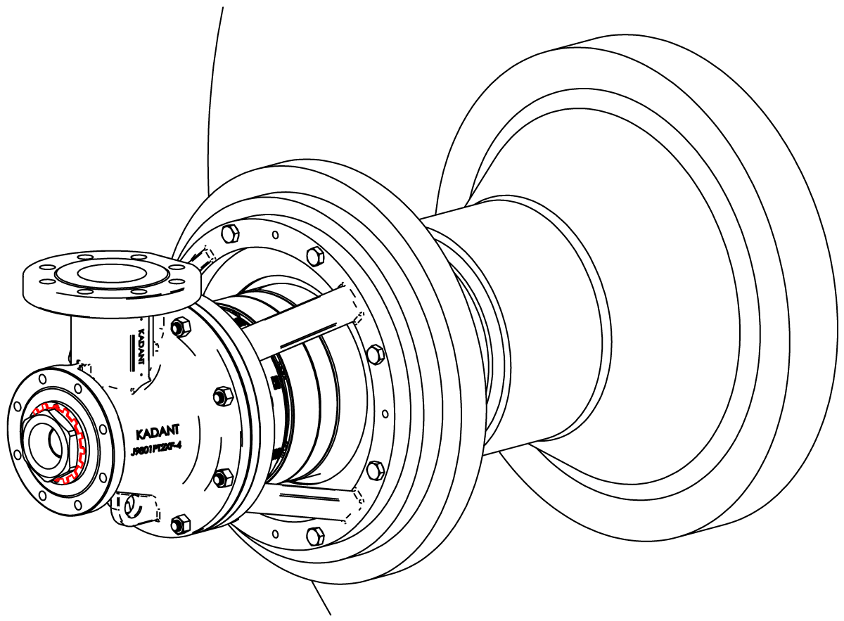
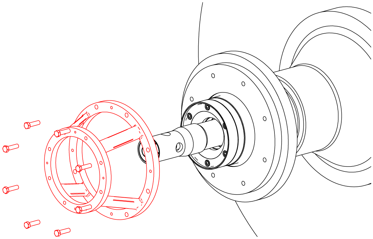
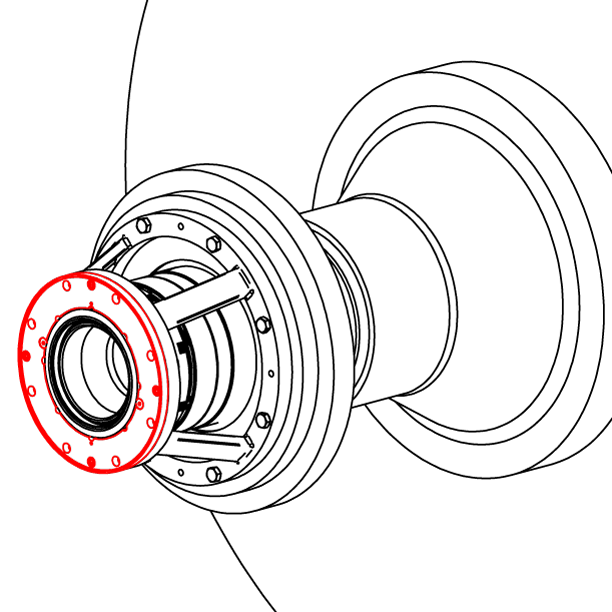
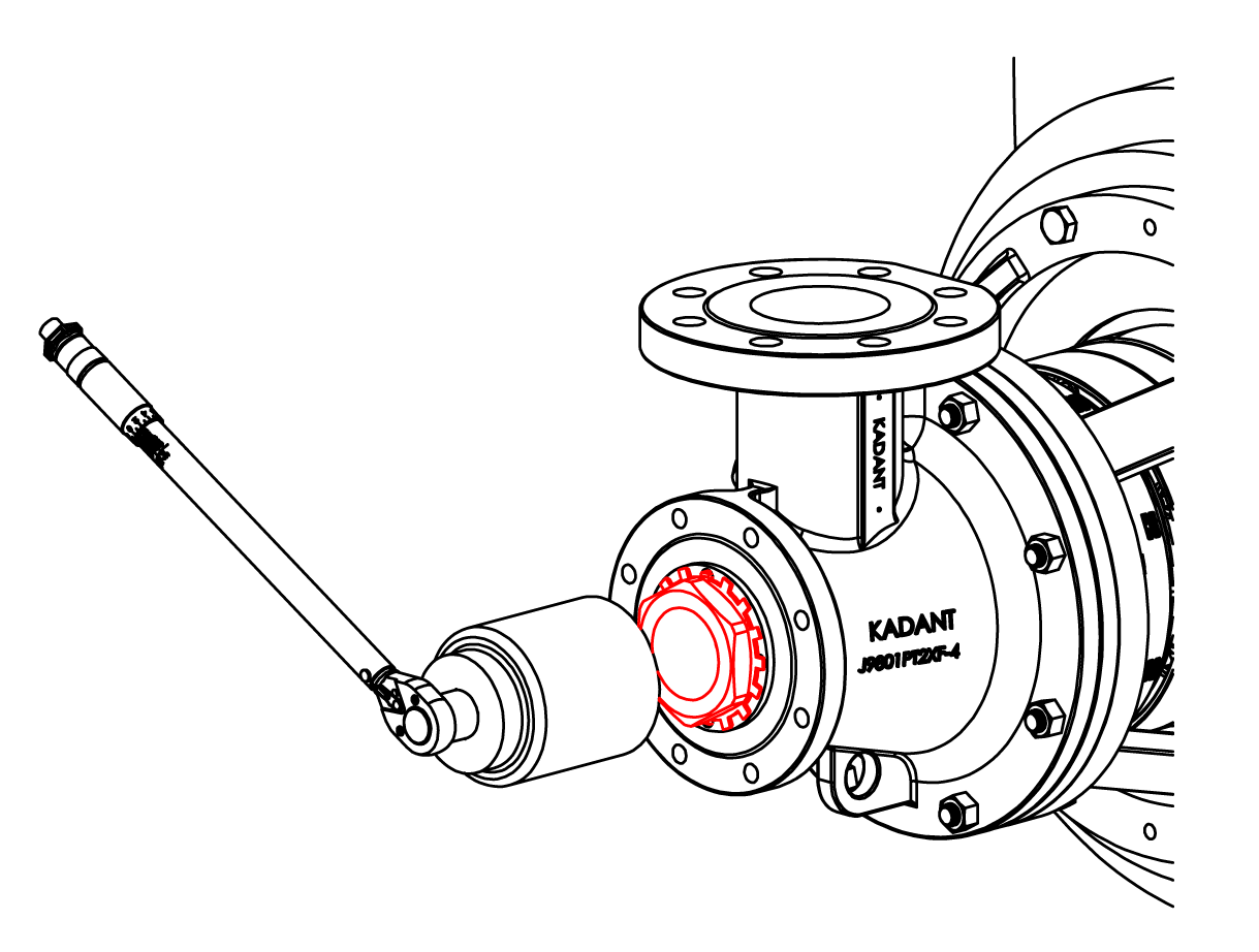
Remove the end cap assembly and seal ring. Place the end cap assembly with the seal ring side up. Move the support tube into the journal if working on the dryer bearing.
Note: Seal ring is fragile and should be handled with care.
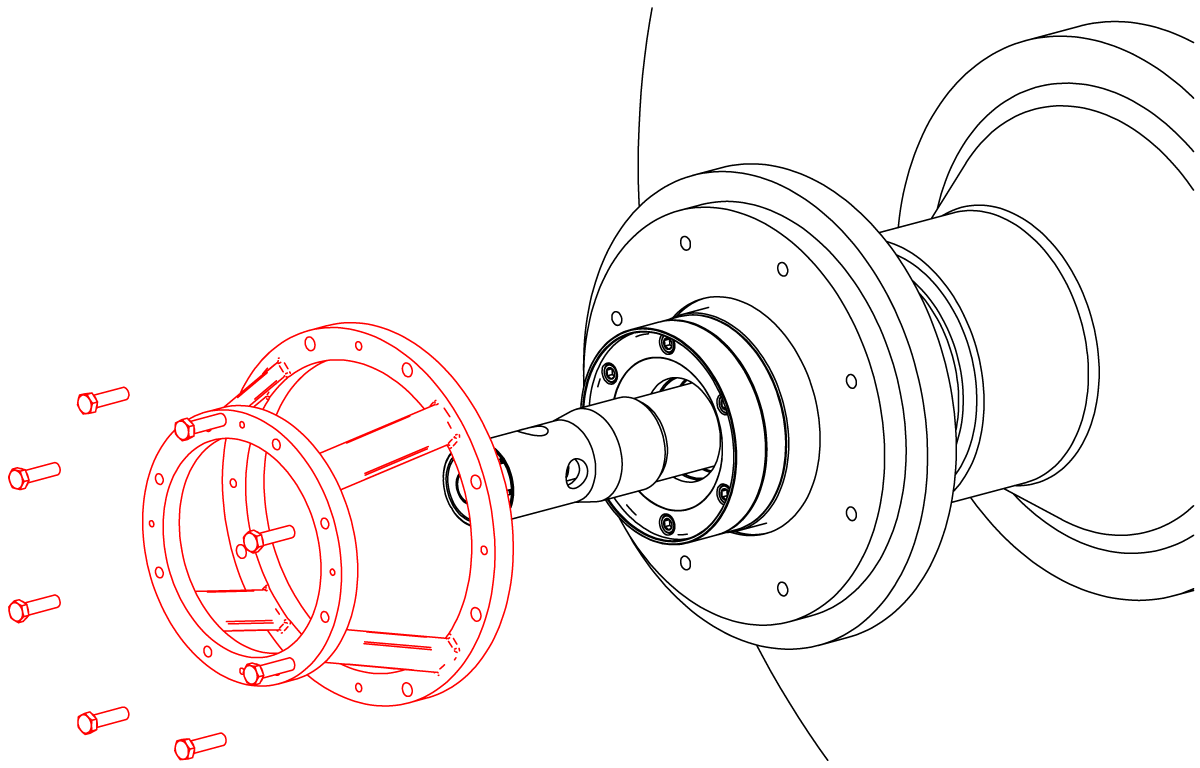
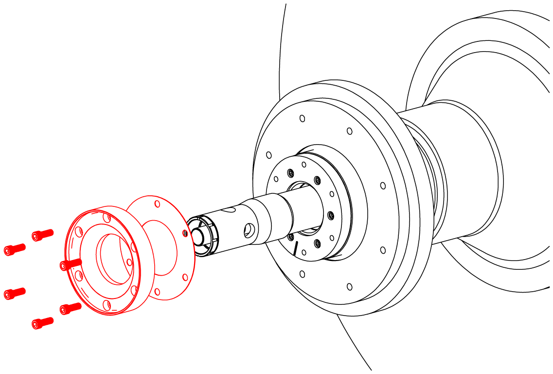
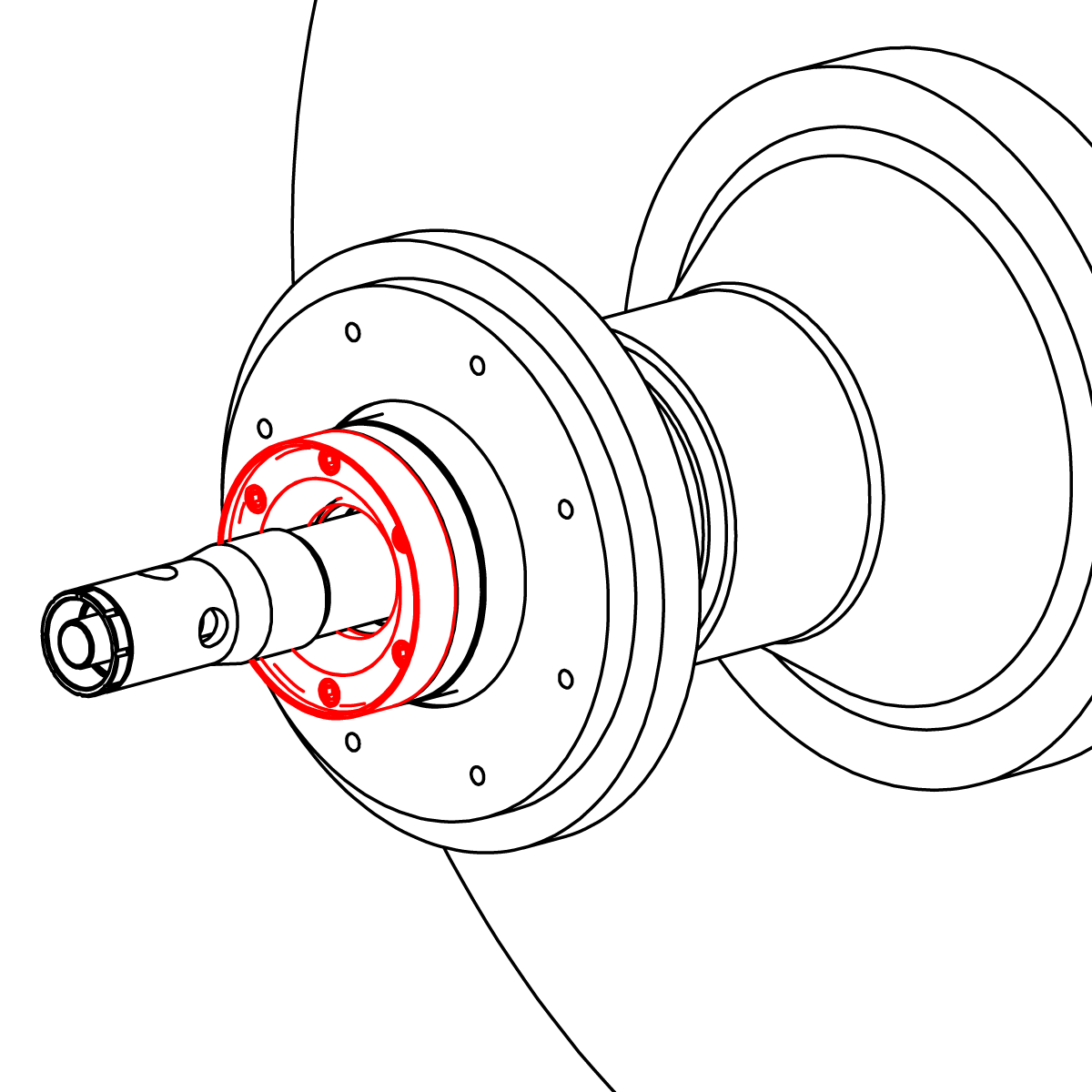
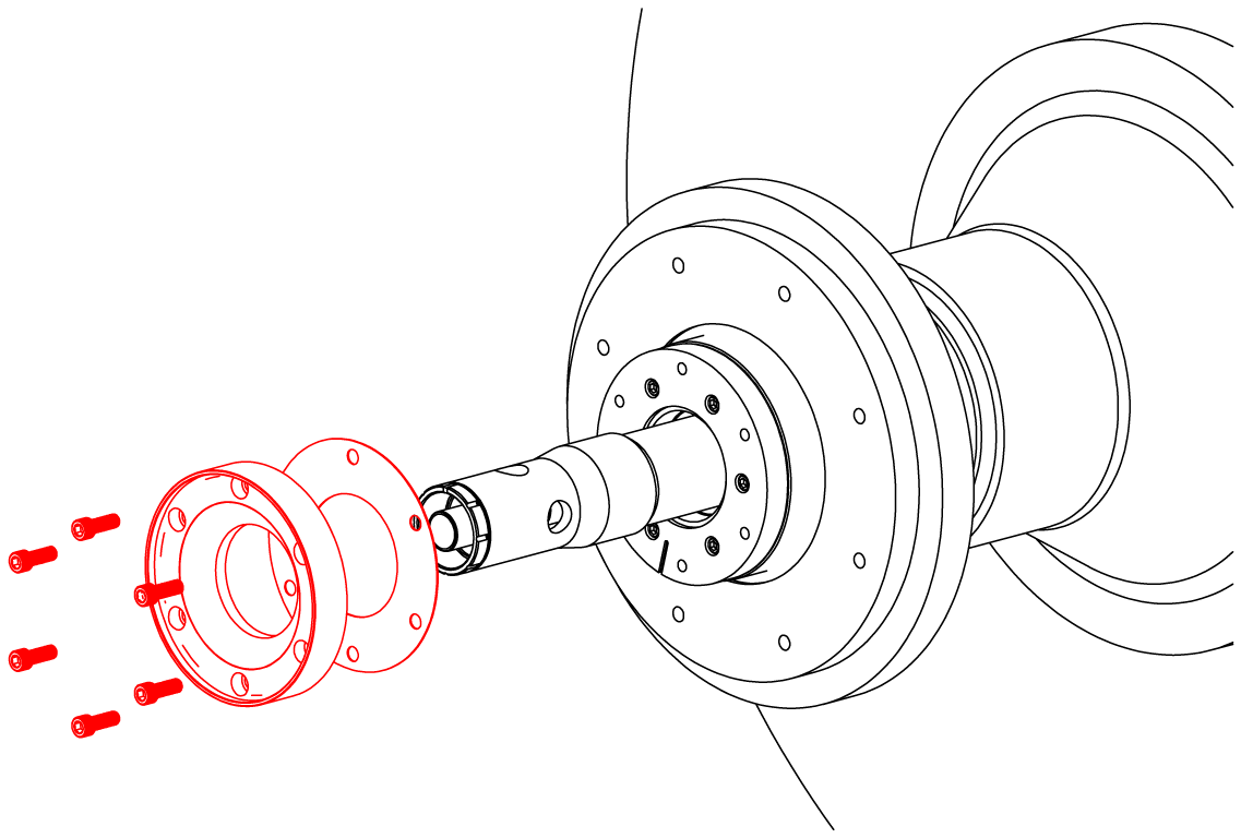
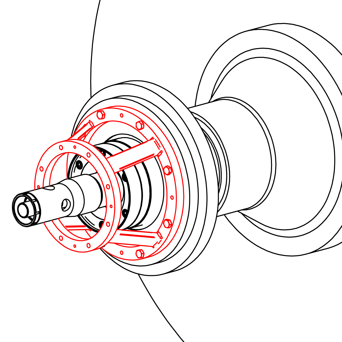
Remove the ring bracket and wear plate.
Tip: If dryer bearing work is needed, remove the journal flange (if necessary) and bearing cover to access the bearing. Reinstall after bearing work is complete.
Note: Kadant Johnson provides two types of repair kits. If using the preassembled end cap assembly kit, proceed to
step 12.
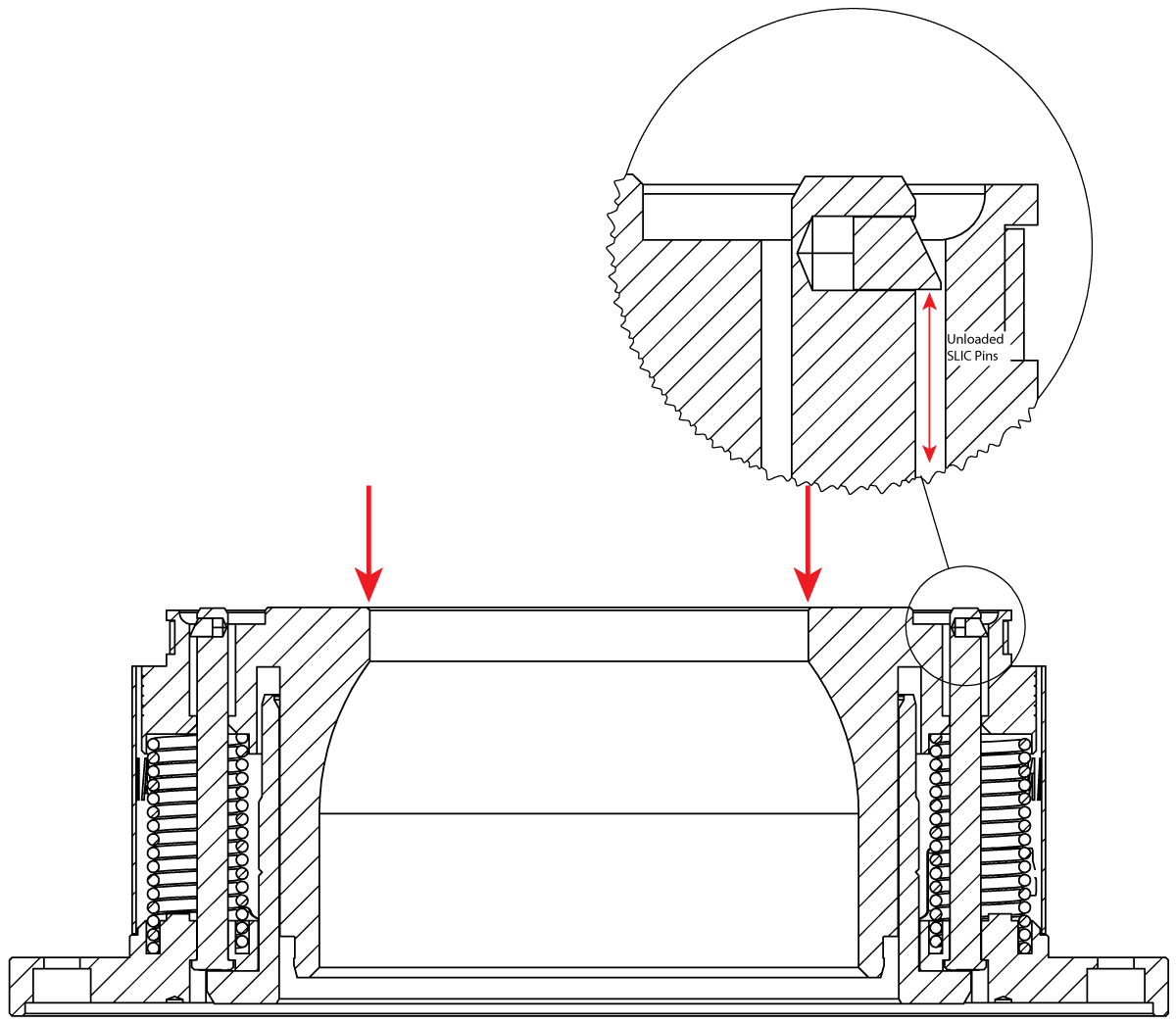
Place the assembly in a press with the seal ring side up. Compress the nipple until the quick release pins are unloaded.
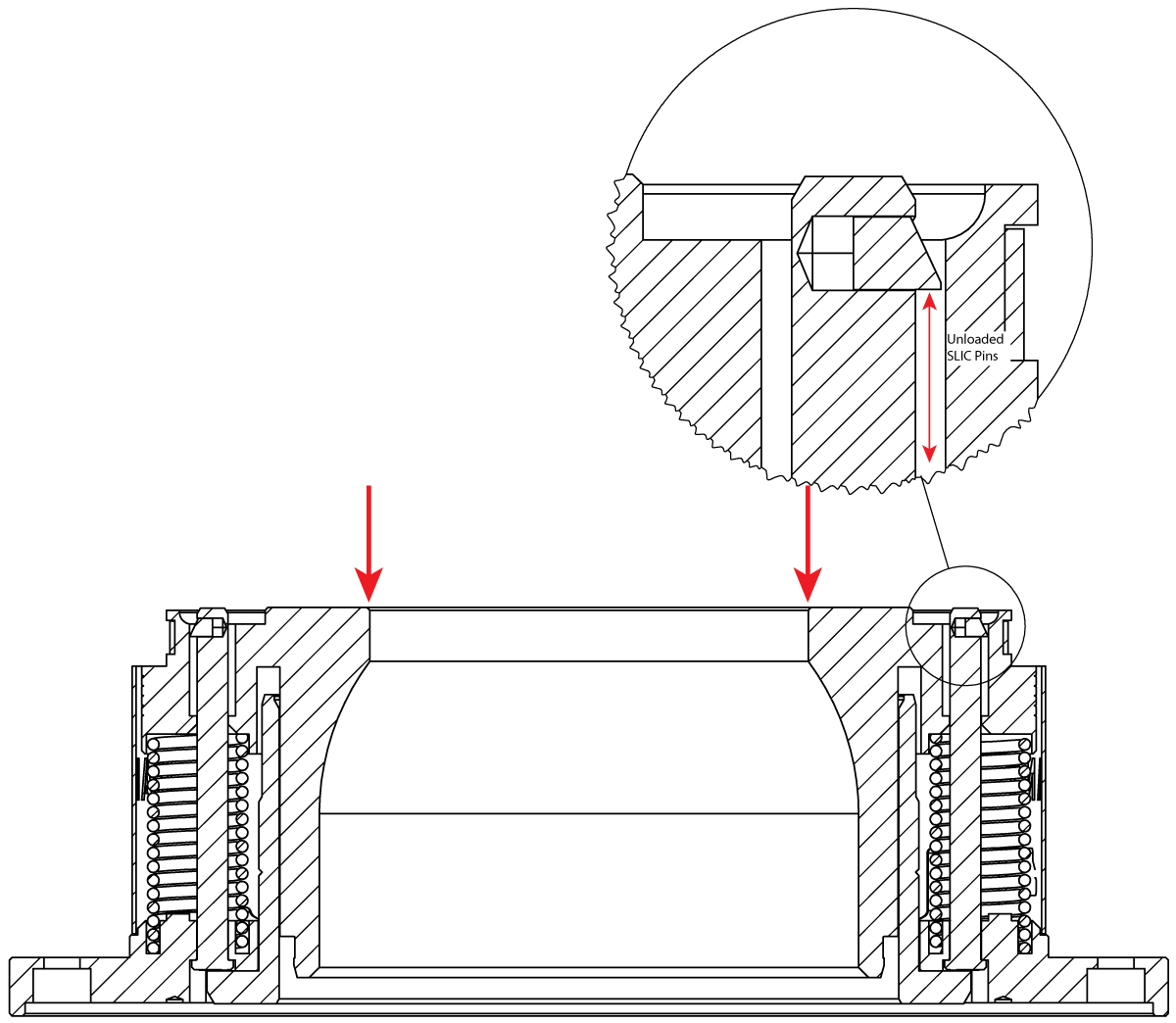
While the nipple is compressed, insert the quick release pin removal tools into the holes until they bottom out. The removal tool will compress the quick release locking mechanism. Release the press until the nipple clears the pins. Separate the nipple from the end cap.
Remove the O-rings or cup seal and discard. Inspect the groove(s) and sealing surfaces. Replace if damaged. Install and lubricate new O-rings or cup seal.
Inspect and clean the end cap, pins, and springs. Replace if damaged.
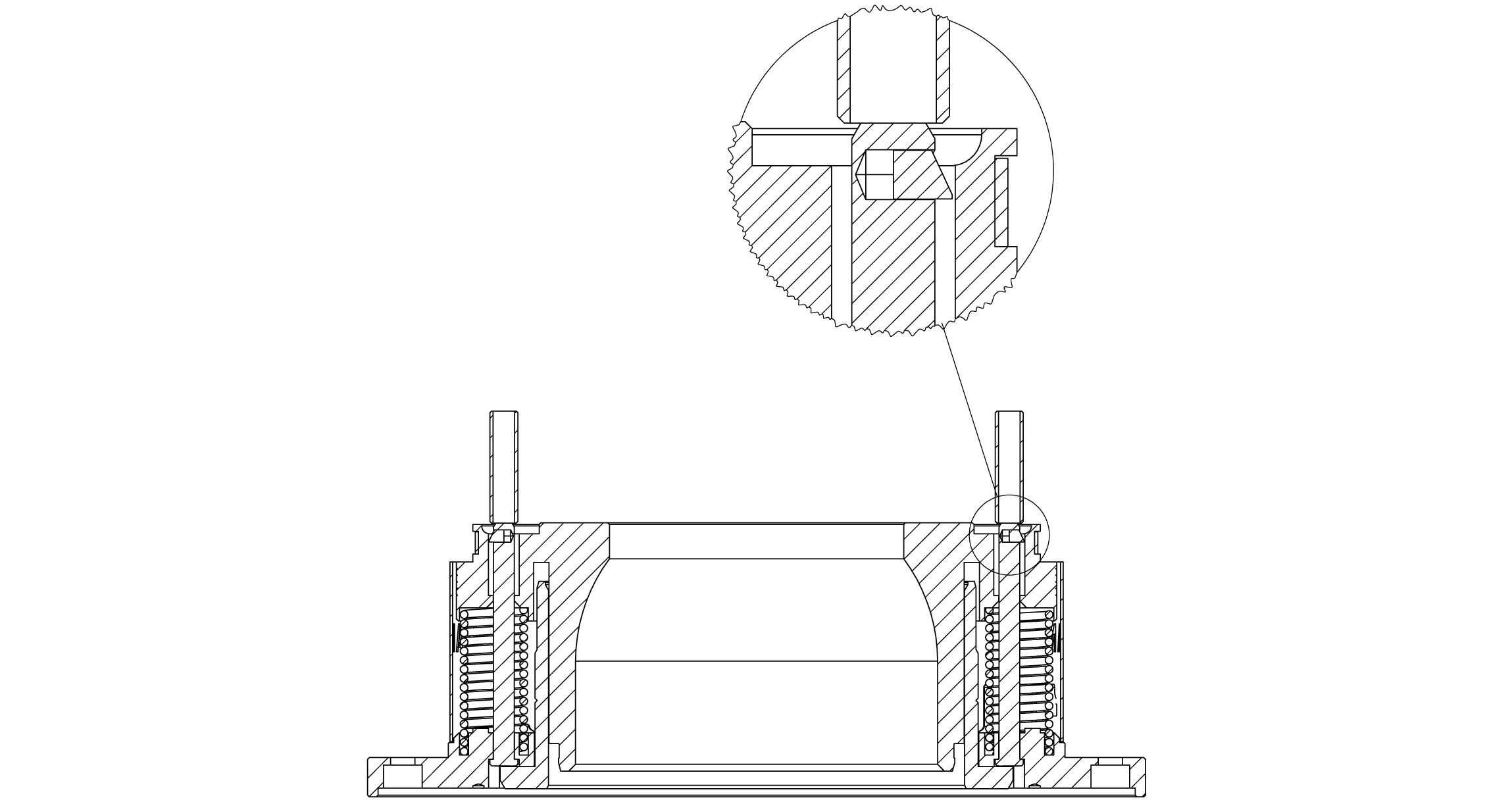
Important: Quick release pins should be installed into the holes with dimples next to them.
Important: If the end cap is damaged, it may be removed form the end flange. Remove the two screws to separate the two. Install a new end cap by reversing the procedure.
Note: Shroud has been removed from image for visual purposes.
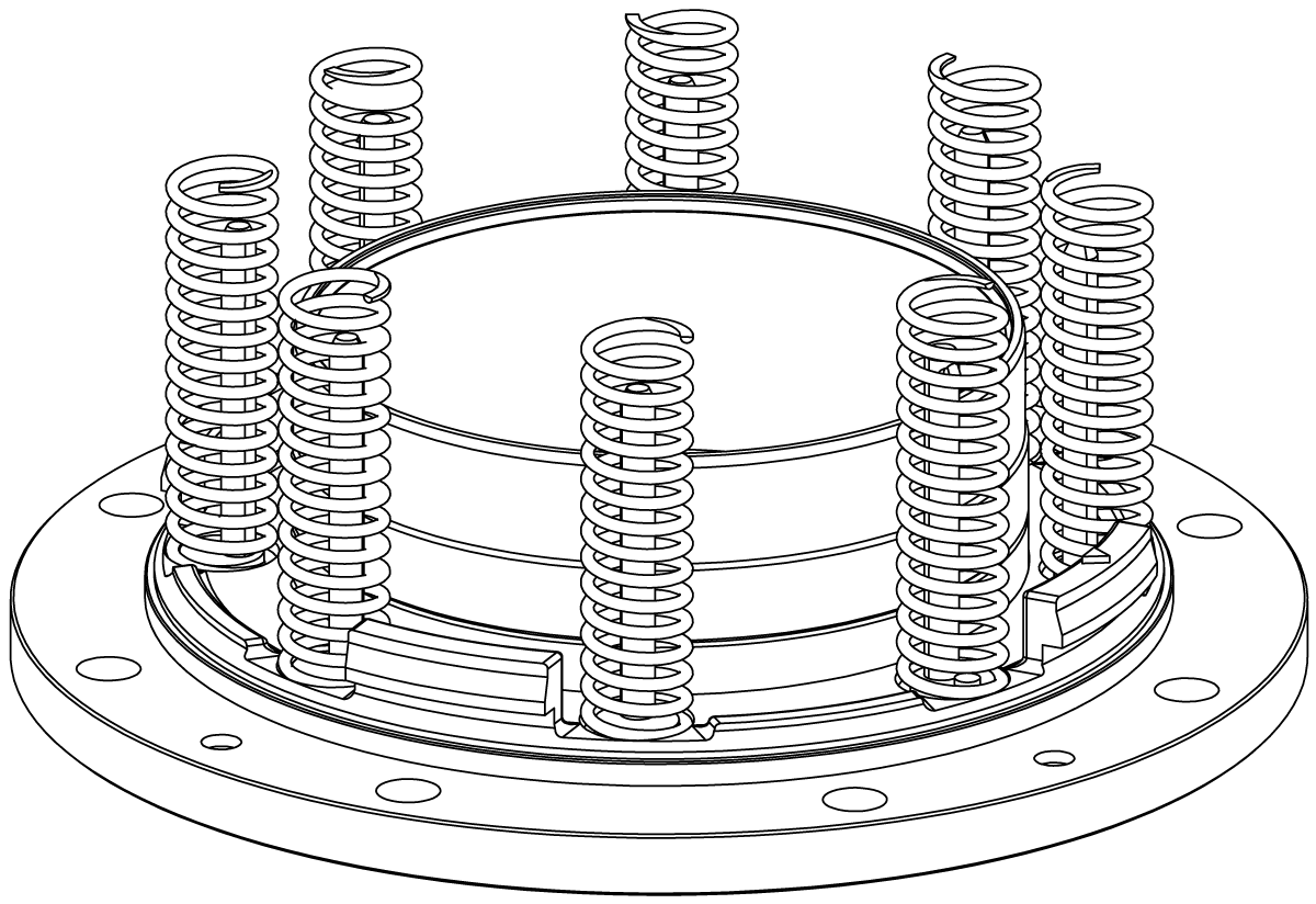
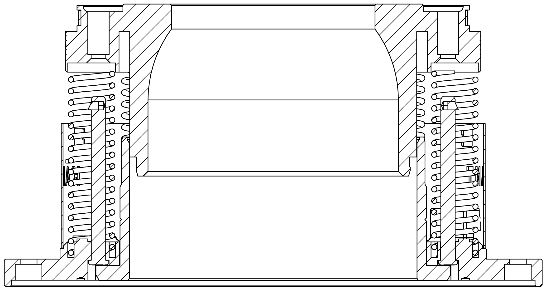
Reinstall the nipple by lining up the larger holes in the nipple with the dimples on the end flange. Use a press to compress the nipple while confirming the springs are seated properly. Continue until the locking mechanism has cleared the bottom of the counter bore. Release the press.
Using a new gasket, reinstall the wear plate (8A) with cap screws (16A).
Tip: Pull the support tube out of the journal if it was pushed in during the previous steps.
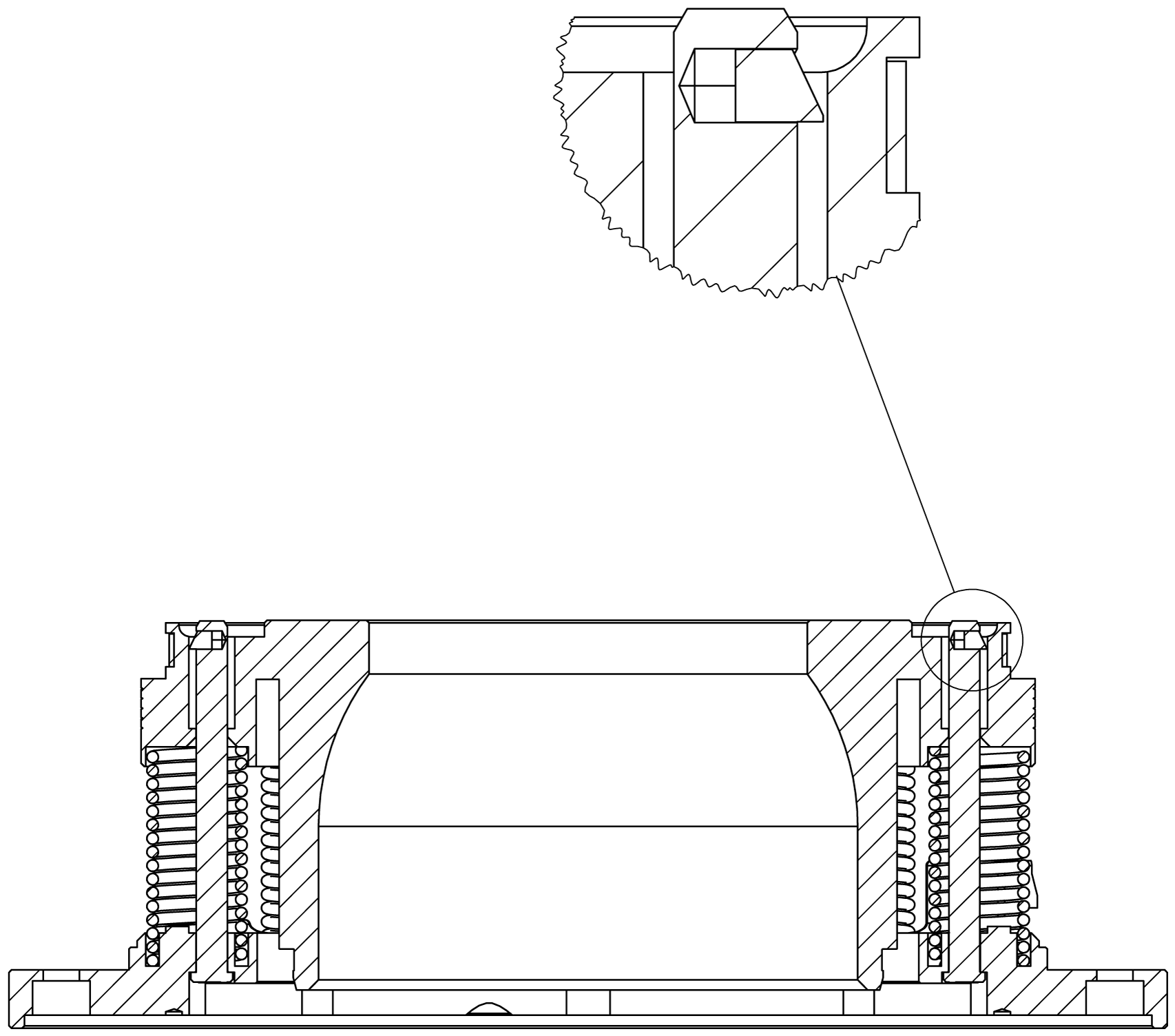
Clean the seal ring surface of the wear plate, new seal ring (6), and nipple. Attach the seal ring and end cap assembly with four cap screws (3C).
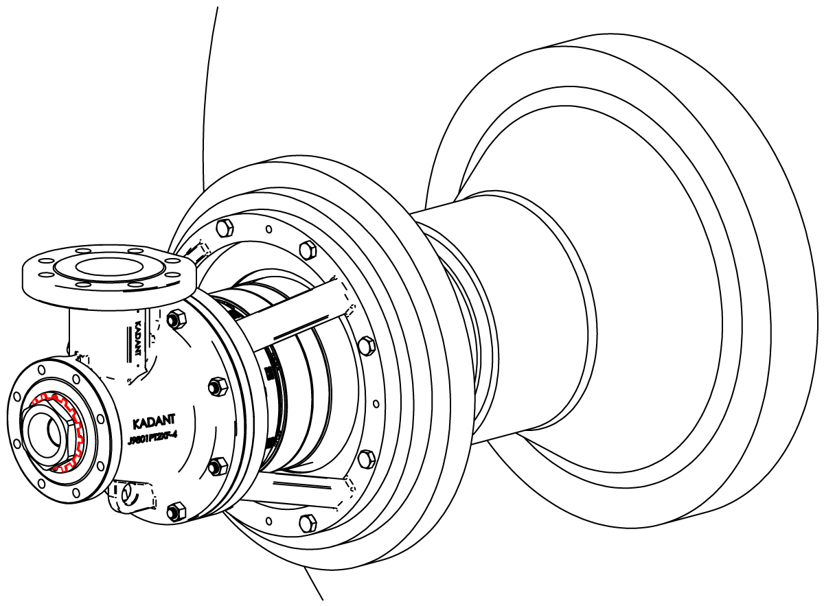
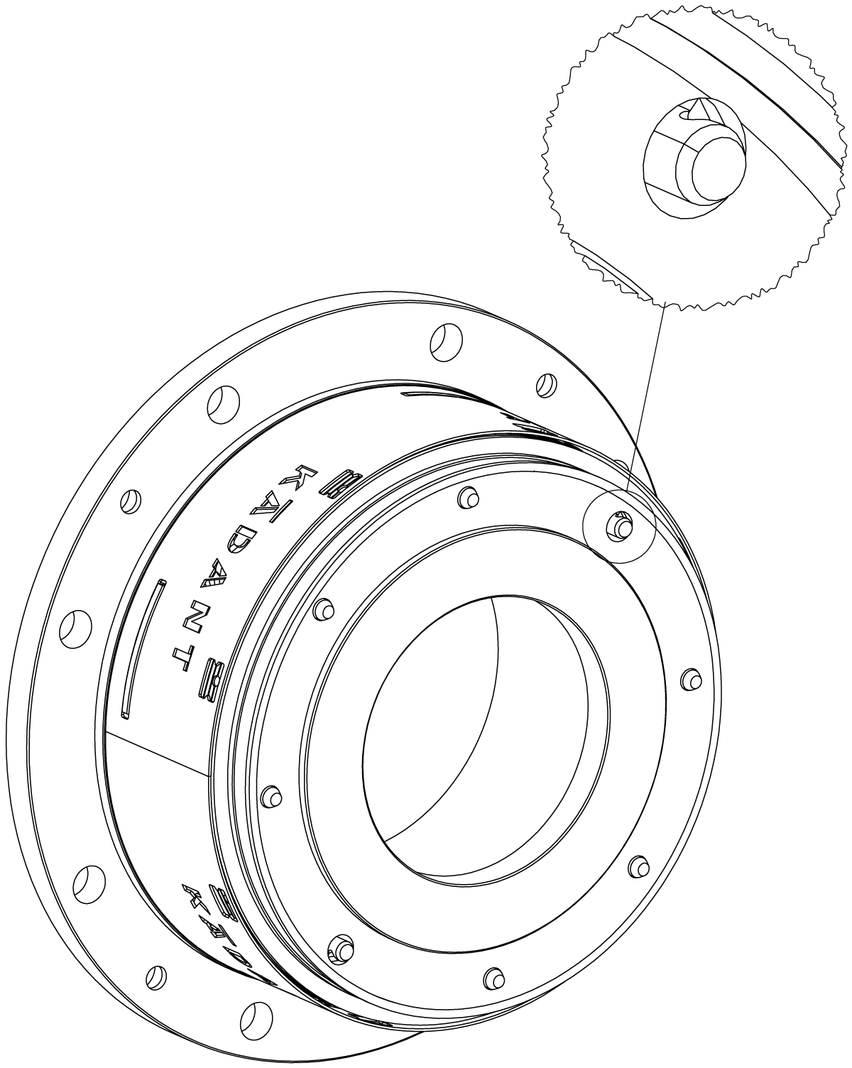
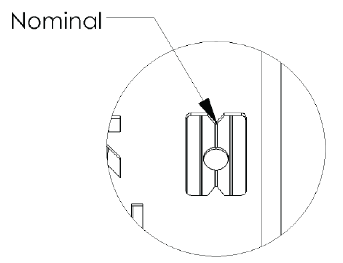
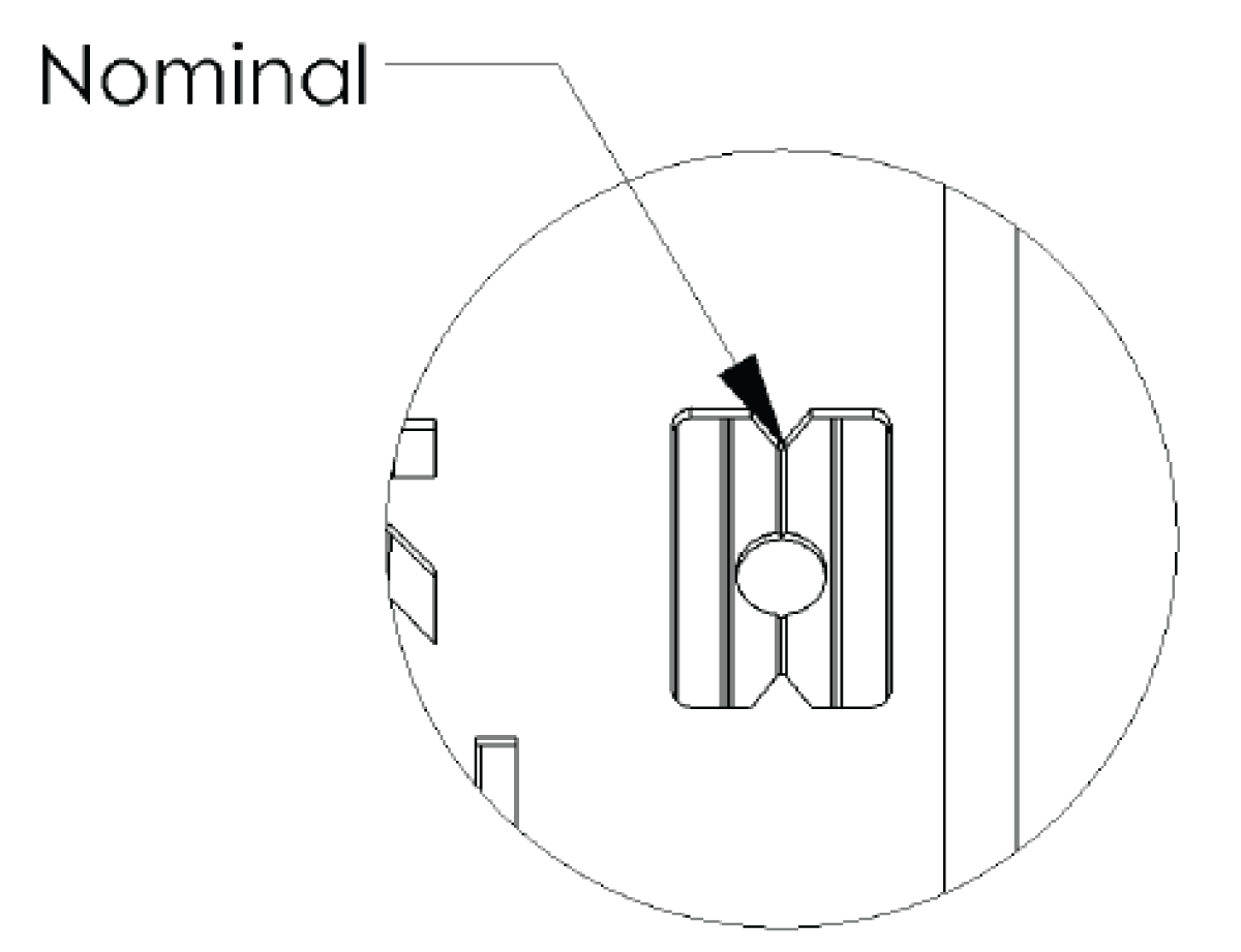
Important: After fastening the end cap assembly, the groove with the dimple should be within the viewing window. If not, the setup dimension is incorrect, please contact Kadant Johnson.
Remove the O-ring from the end of the support tube. Lubricate and install a new O-ring with silicone lubricant. Apply anti-sieze to the tapered portion of the tube.
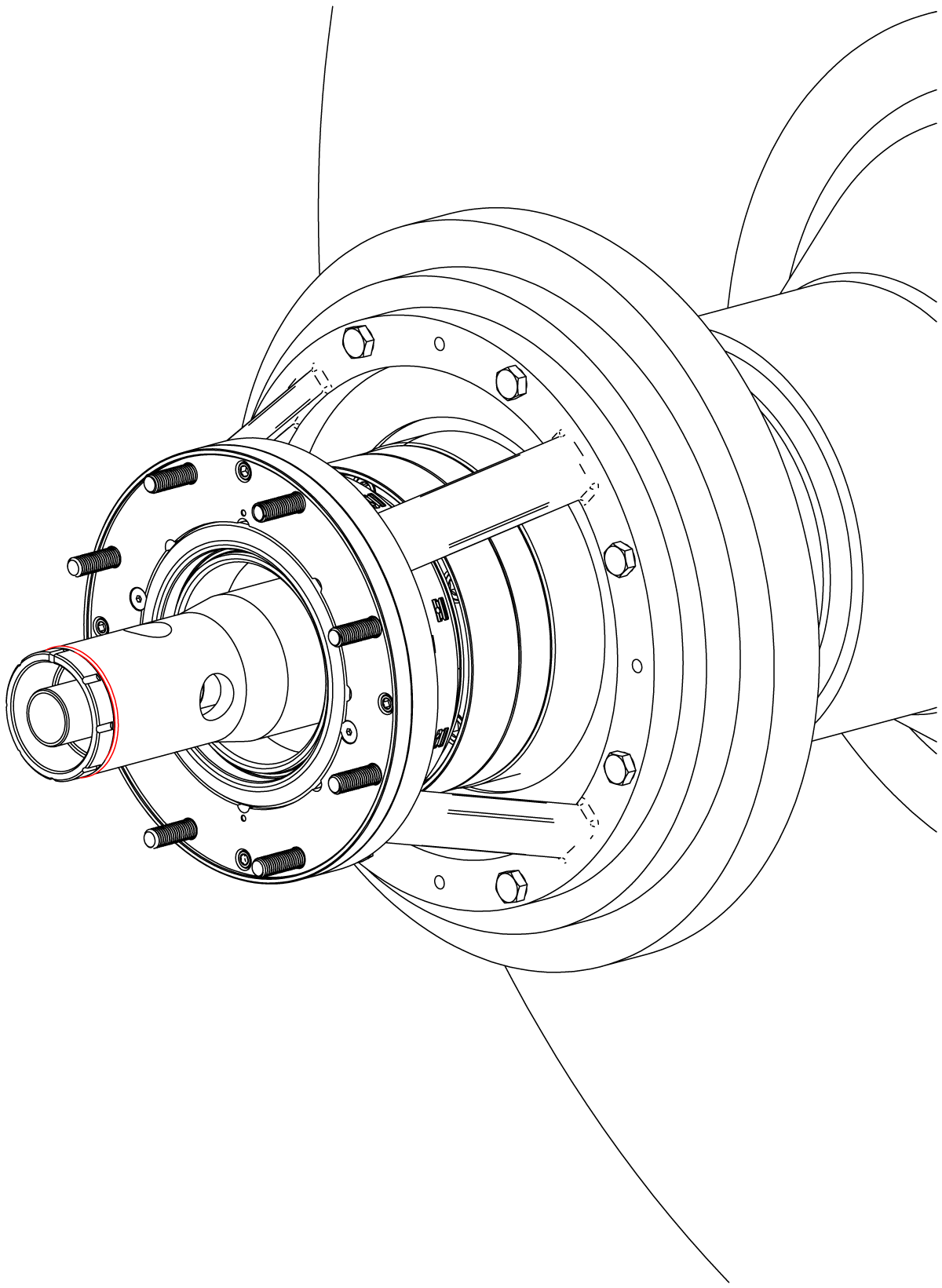
Install a new O-ring (26) into the body. Position the body over the suport tube. Align the pin with the support tube indexing slots. Position both over the studs on the ring bracket and secure with hex nuts (20B).
Important: The indexing slot should be installed in the same position as noted in step 3.
Install a new O-ring in the support tube nut and apply anti-seize to the threads. Insert two bent lock washer tabs into the body and install support tube nut, torque to 400 ft-lbs (542 Nm). Bend two lock washer tabs over the bolt flats.
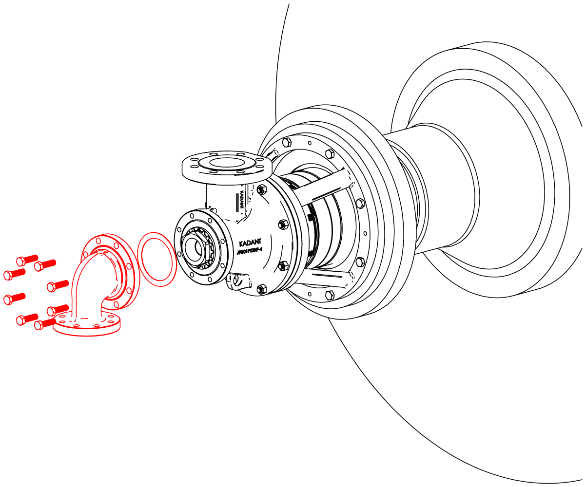
Place gasket (8) on head and install head on body with cap screws (2A). Connect piping.
R-9800PT2X-1

