Read all of the instructions before proceeding.
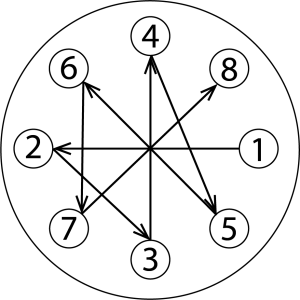
Refer to Kadant Johnson assembly drawing for part identification and to drawing A37640 for torque specifications. For easy identification, parts used in individual steps are often accompanied with their position in the assembly drawing [e.g. gasket (8B)]. Tighten all fasteners in a star pattern. Certified drawings are available upon request. Dimensions are for reference only and subject to change.

Remove existing equipment. Clean journal gasket surface. Chase and clean tapped holes. If necessary remove bearing cover.

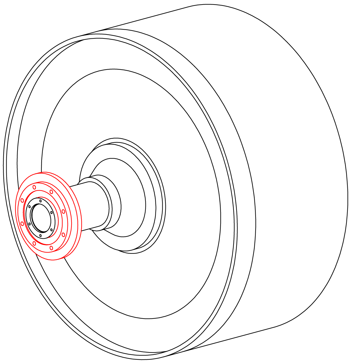
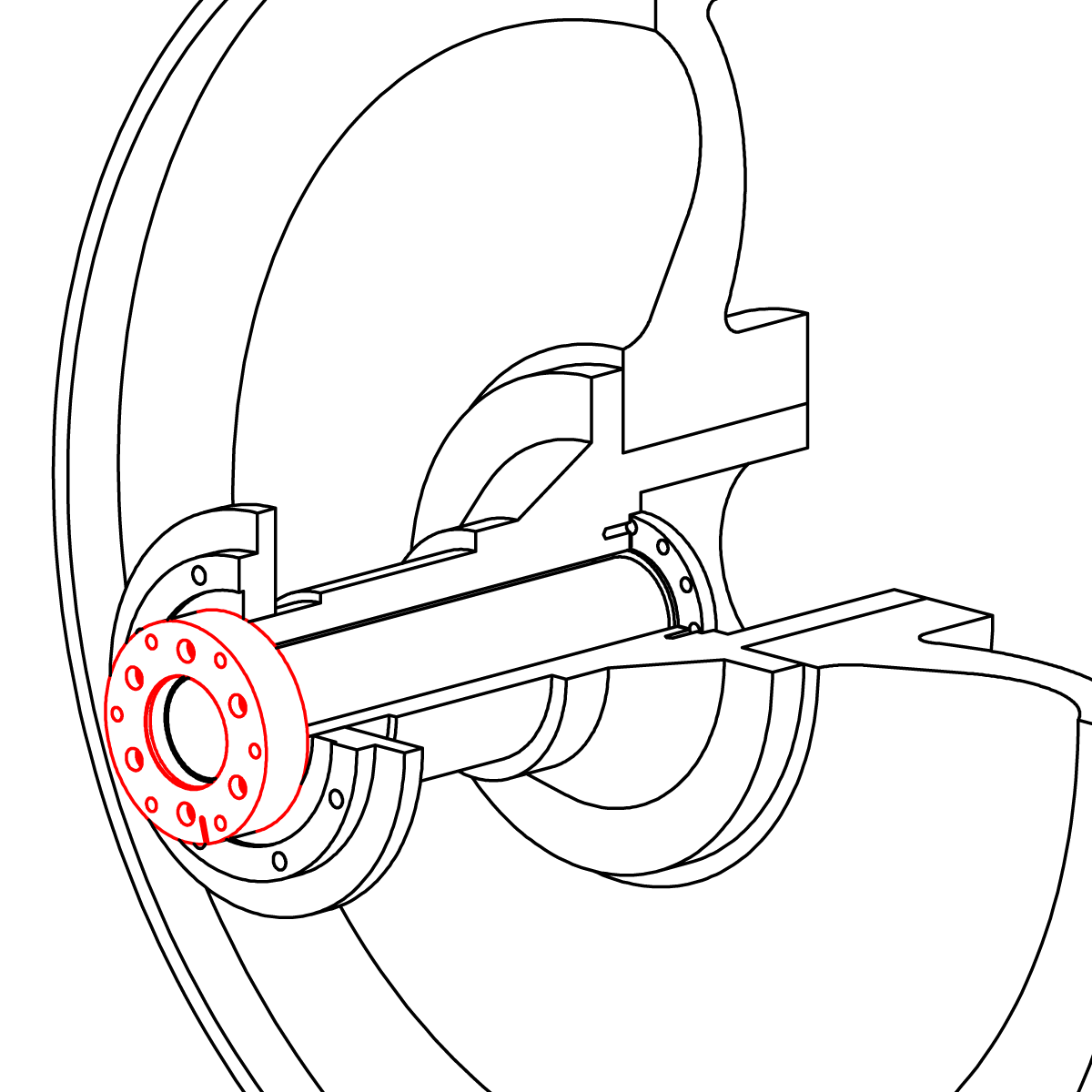
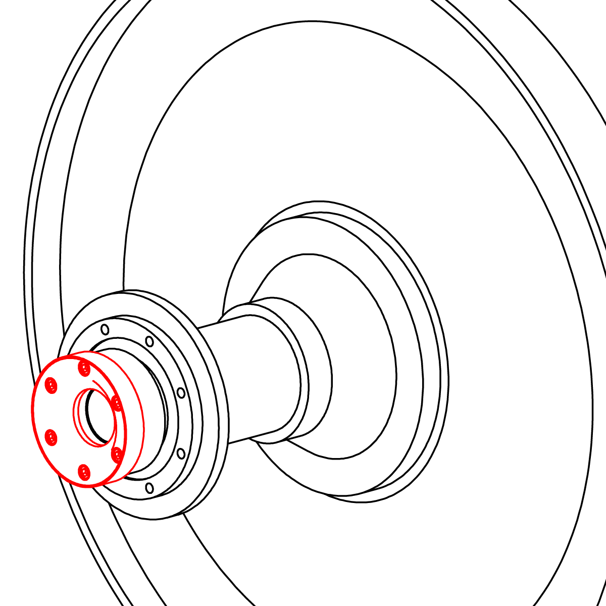
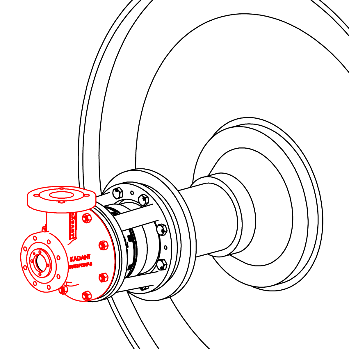
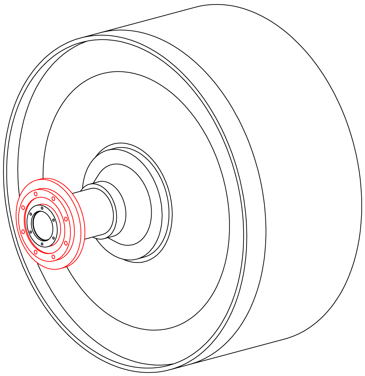
If installing insulating sleeve, refer to “Insulating Sleeve Installation Instructions.” Place journal flange, gasket (8B), and filler flange (if necessary) onto journal and secure using cap screws (5A).
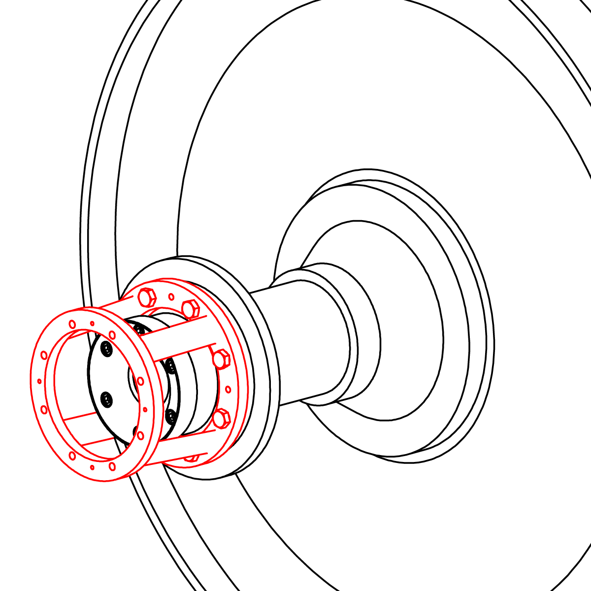
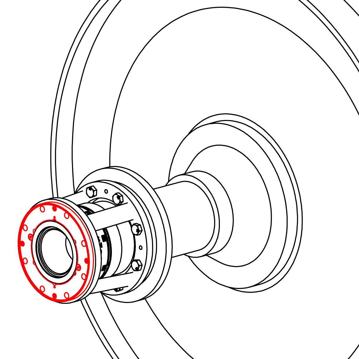
Clean the mating surfaces of the wear plate, seal ring (6) and nipple (4). Attach the seal ring and end cap assembly with four cap screws (3C).
Tip: From the inside of the seal ring, use your finger tips to balance the seal ring while installing the end cap assembly.
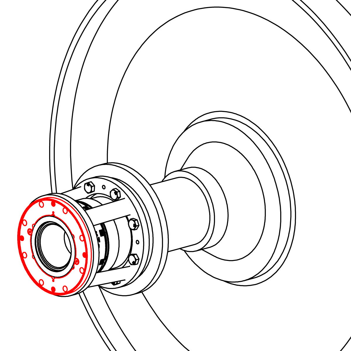
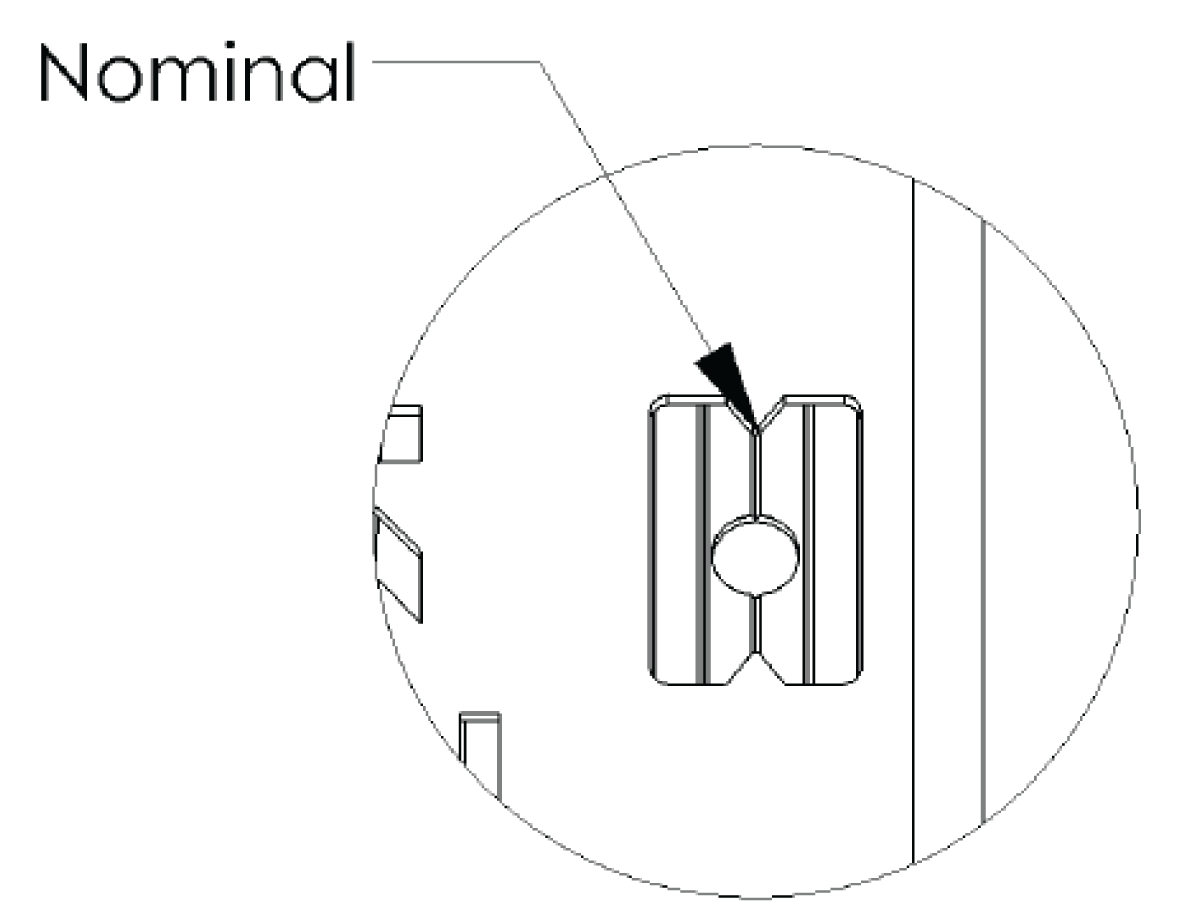
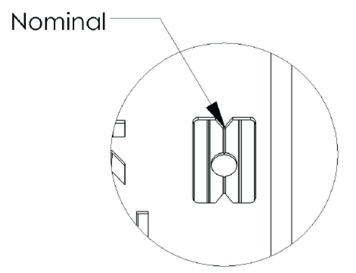
Important: After fastening the end cap assembly, the groove with the dimple should be within the viewing window. If not, the setup dimension is incorrect, please contact Kadant Johnson.
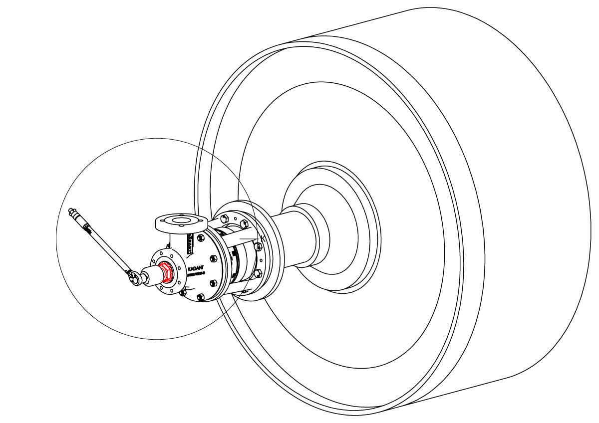
Insert support tube from outside dryer. This requires adequate clearance between the dryer hood and the journal.
Remove support tube nut and lubricate with anti-seize.
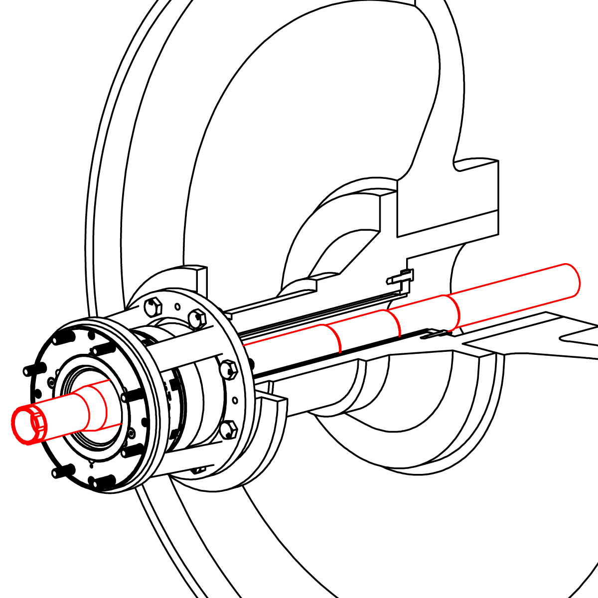
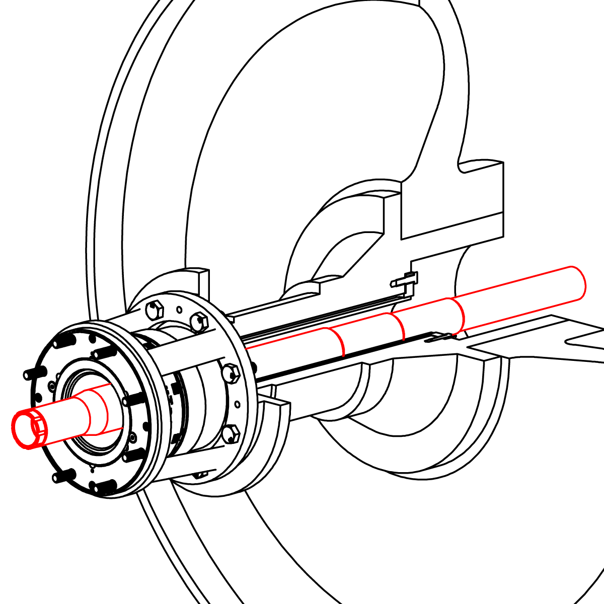
Insert plane end of support tube through rotary joint and journal bore. Leave tapered end protruding from end cap 7" (178 mm). Apply anti-seize to the tapered portion of the support tube. Lubricate pre-asssembled body and support tube O-ring with silicone lubricant.
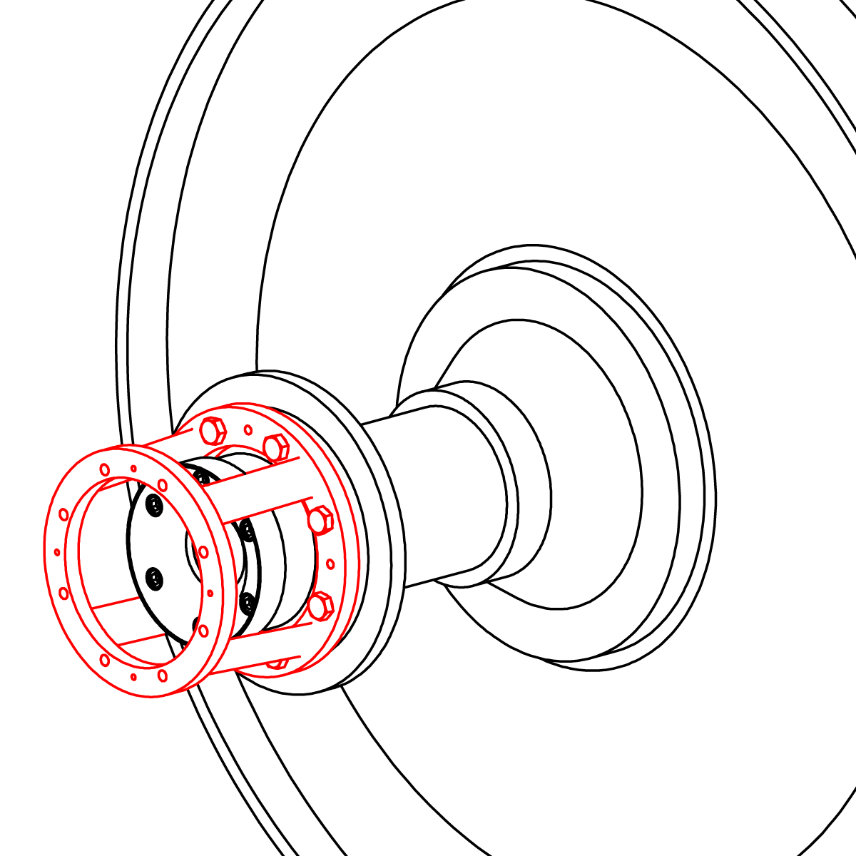
Position the body over the support tube and align the pin with the support tube indexing slots. Position both over studs on the ring bracket and secure with hex nuts (20B).
IMPORTANT: The support tube must be installed with the indexing slot at the 12 o’clock position.
Insert two bent lock washer tabs into the body and install support tube nut, torquing to 300 ft-lbs (407 Nm). Bend two lock washer tabs over the bolt flats to prevent bolt loosening.
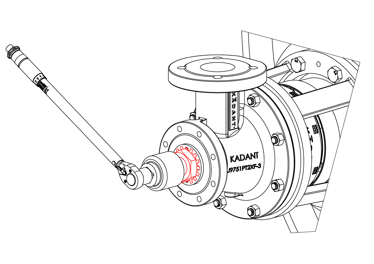
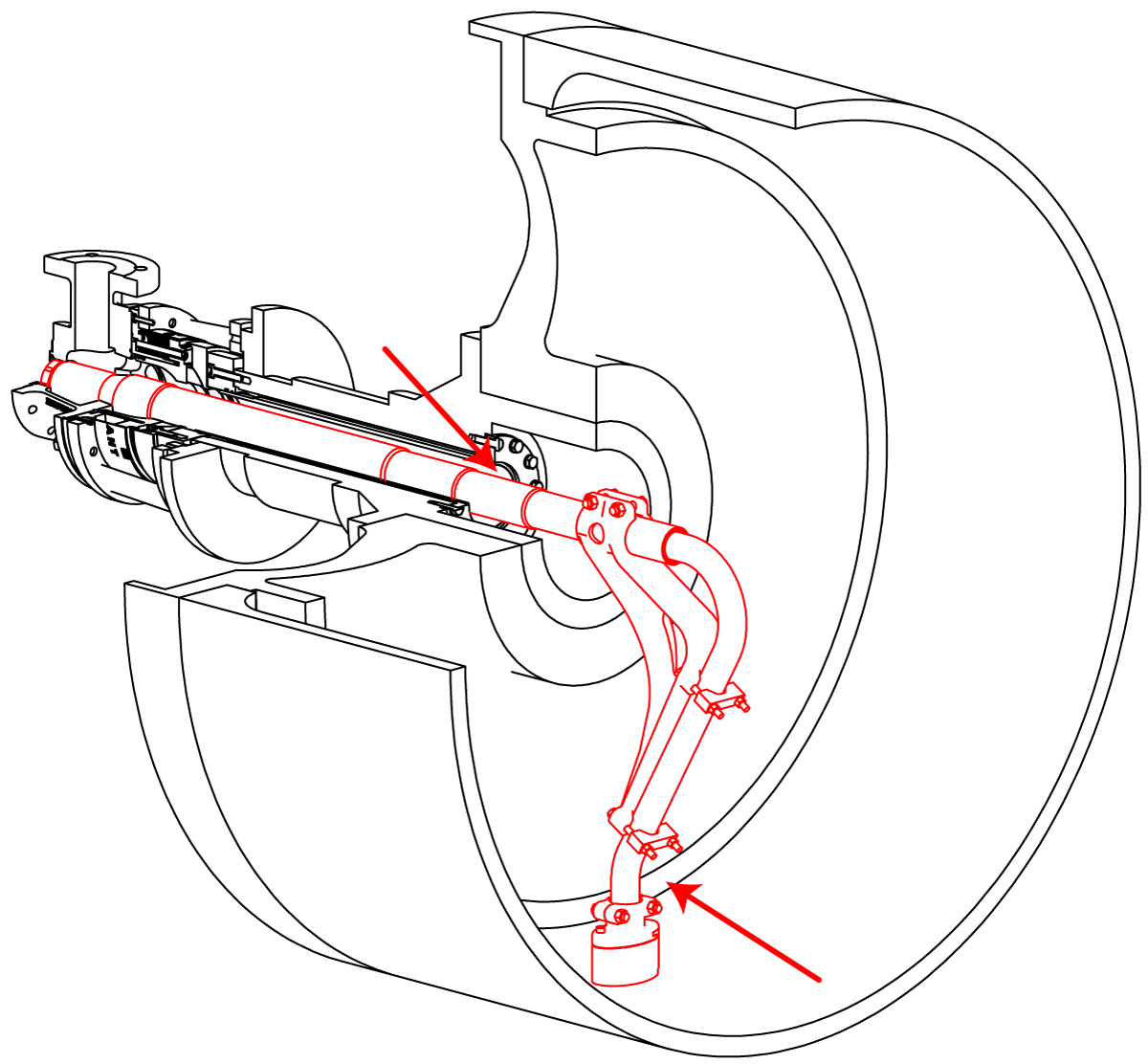
From inside the dryer, apply silicone lubricant to the O-ring. Slide pick-up fitting onto the vertical syphon pipe.
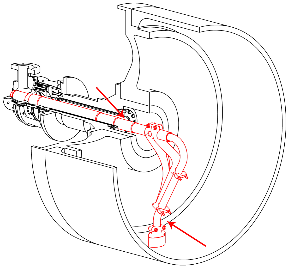
Slide the vertical syphon pipe into the support tube until it passes through the O-ring and the support bracket is over the support tube. Secure the vertical syphon pipe using clamps.
Final Syphon Adustment.
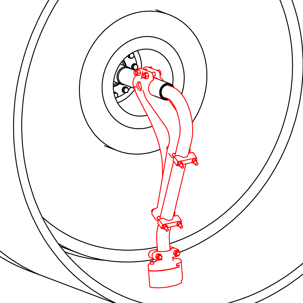
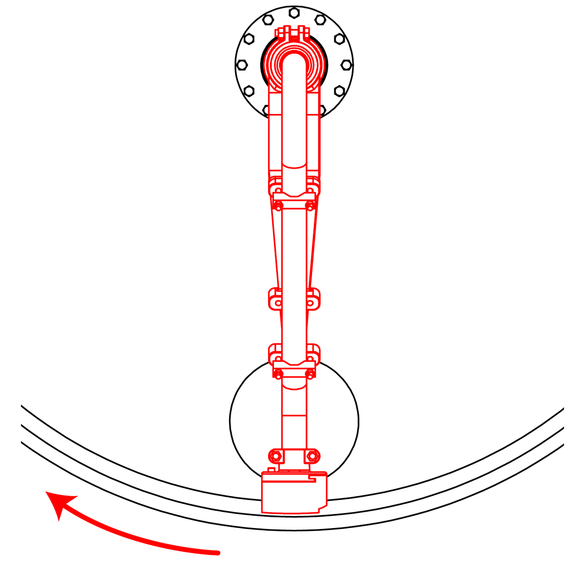
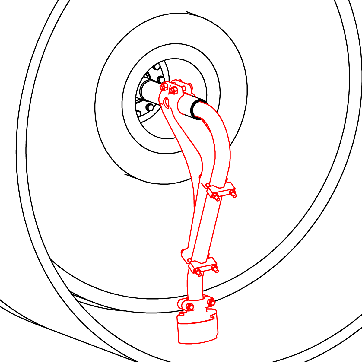
Check support bracket is vertical and syphon pick-up fitting is at the bottom of the dryer and pointed into the rotation of the dryer. Adjust circular portion of the support tube bracket so that it is 4" (102 mm) from the end of the support tube. If the dryer has a groove, center the pick-up foot in the groove. Set the pickup clearance per Kadant Johnson specifications using a gauge. Secure by tightening cap screws/hex nuts.
Make sure the syphon clears all obstructions, including counter weights, manway, and Turbulator® Tube™ bars.
Check the support tube clearance through the journal is at least 3/16" (5 mm). Tighten support bracket clamp cap screws to 50 ft-lbs (68 Nm).
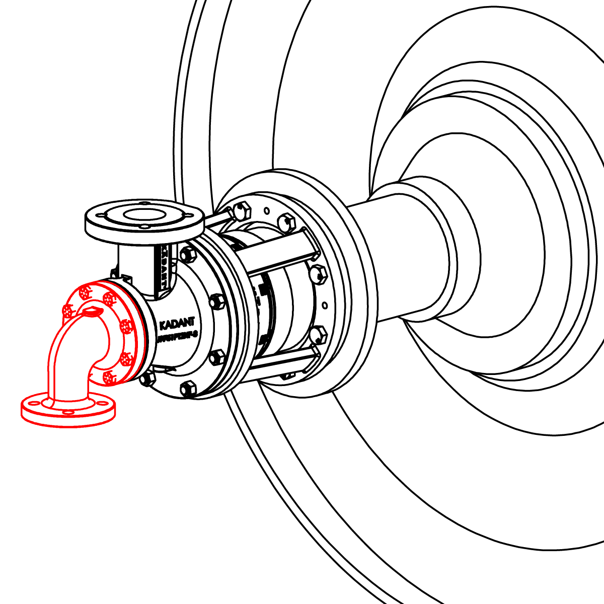
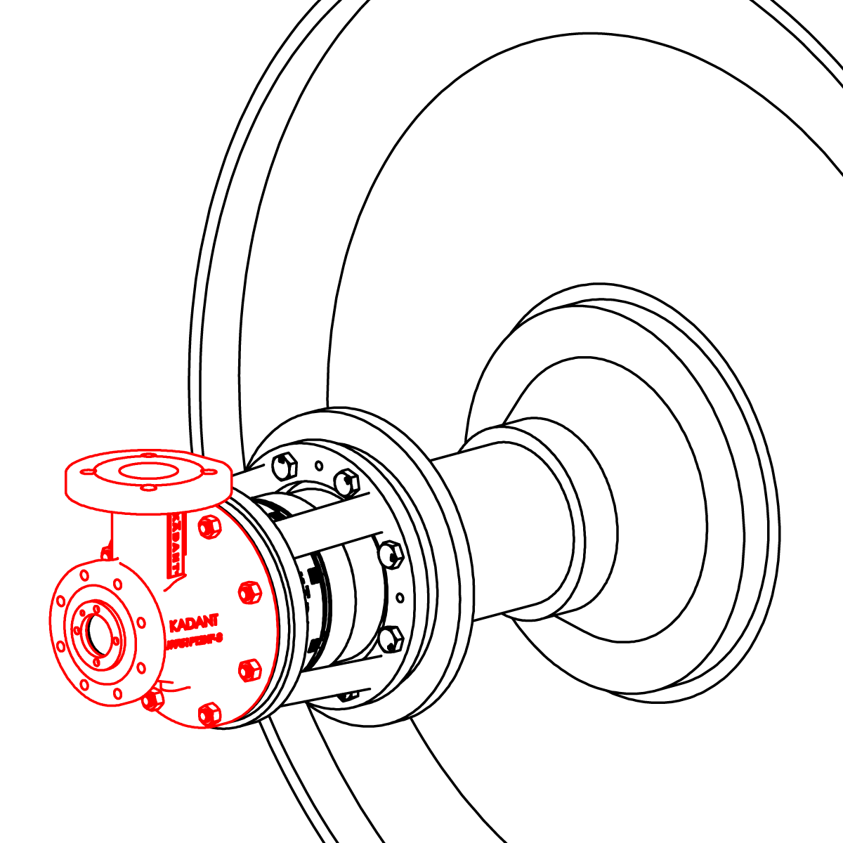
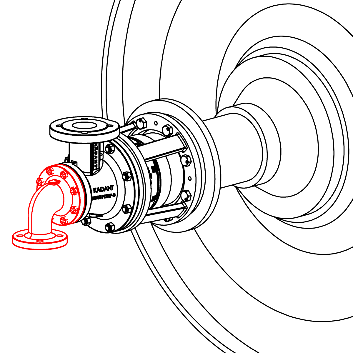
Place gasket (8) on head and install head on body with cap screws (2A). Pipe the rotary joint.

