Read all of the instructions before proceeding.
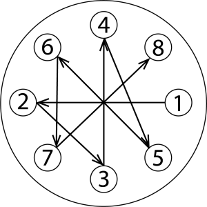
Refer to Kadant Johnson assembly drawing for part identification and to drawing A37640 for torque specifications. For easy identification, parts used in individual steps are often accompanied with their position in the assembly drawing [e.g. gasket (8B)]. Tighten all fasteners in a star pattern. Certified drawings are available upon request. Dimensions are for reference only and subject to change.

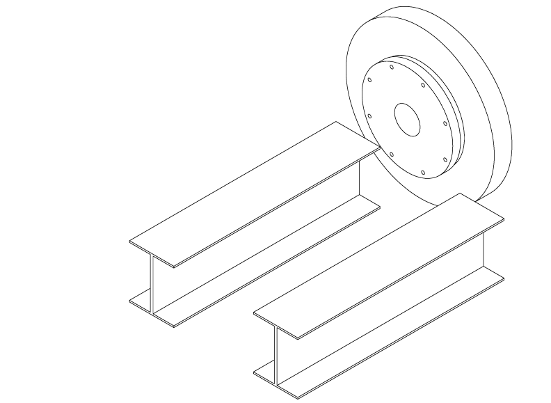
Remove the existing equipment.
Note: Not all installations use a new journal flange. Consult Kadant Johnson drawings prior to installation.
Note: Existing framework may need modification. Consult Kadant Johnson prior to installation.

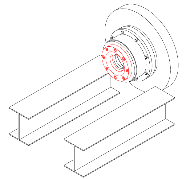
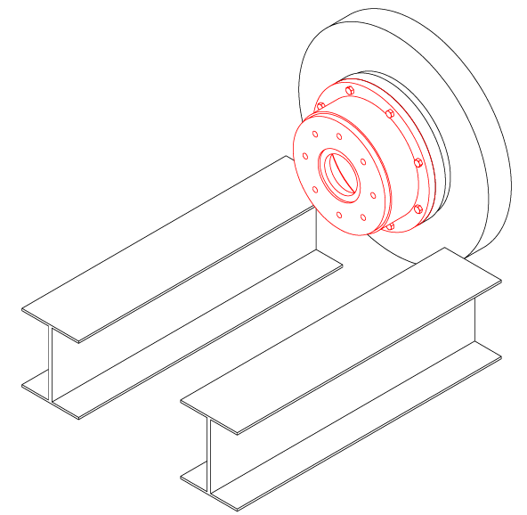
If applicable, install a new journal flange using a new gasket.

Install the wear plate using a new gasket.
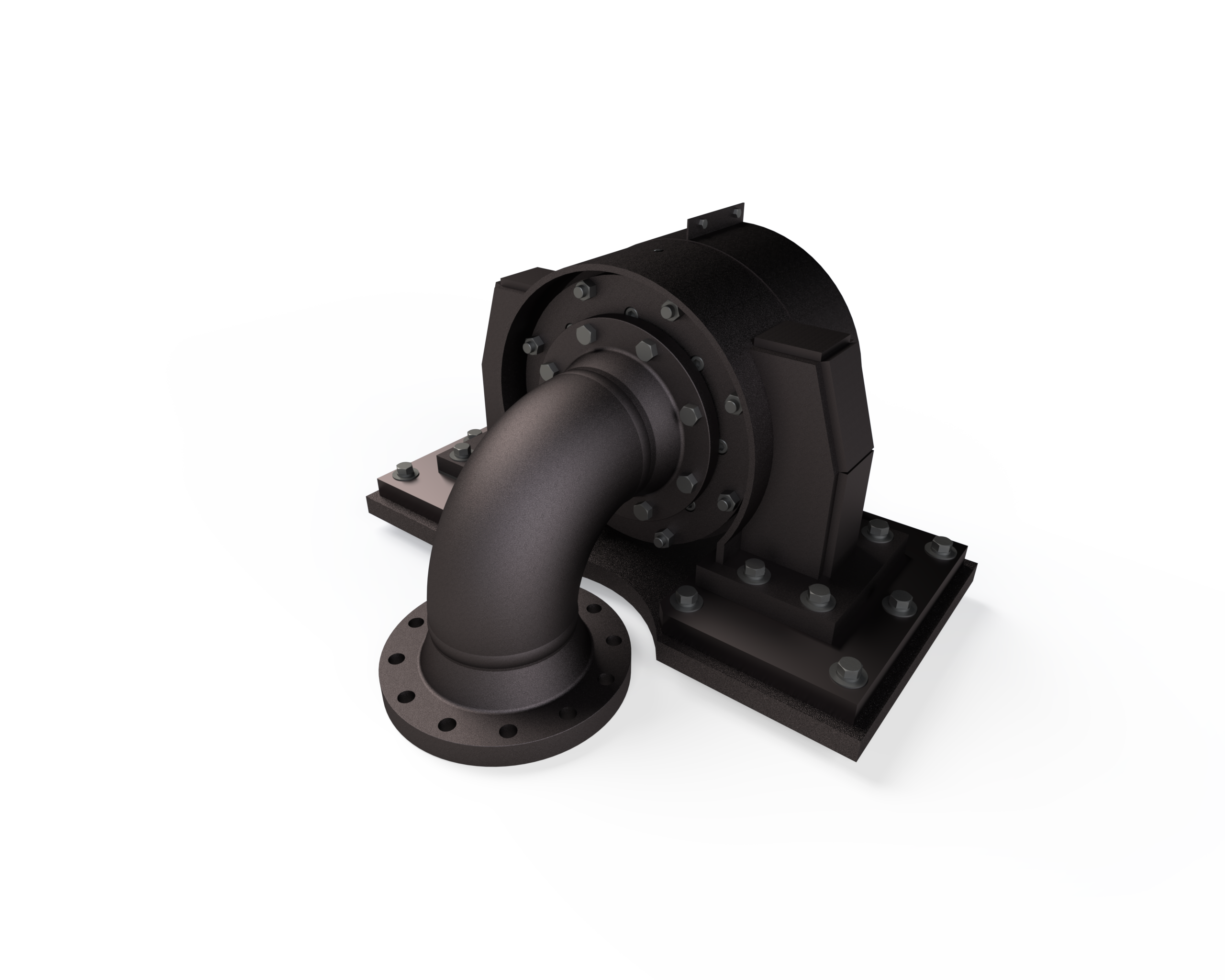
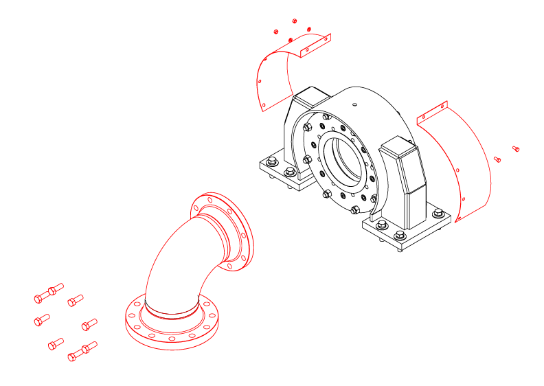
The rotary joint is shipped partially assembled. If equipped with a guard, remove it. The head (2) may be removed for ease of installation.

Bracket mounting is machine specific. Consult Kadant Johnson drawings before proceeding. If using adjustable plates, install those first.
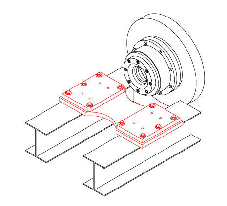
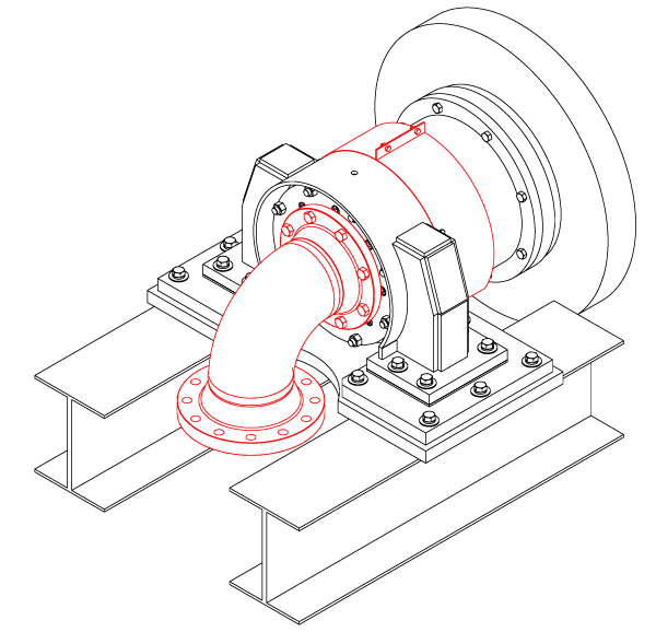
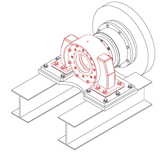
Install the bracket with the end cap assembly.

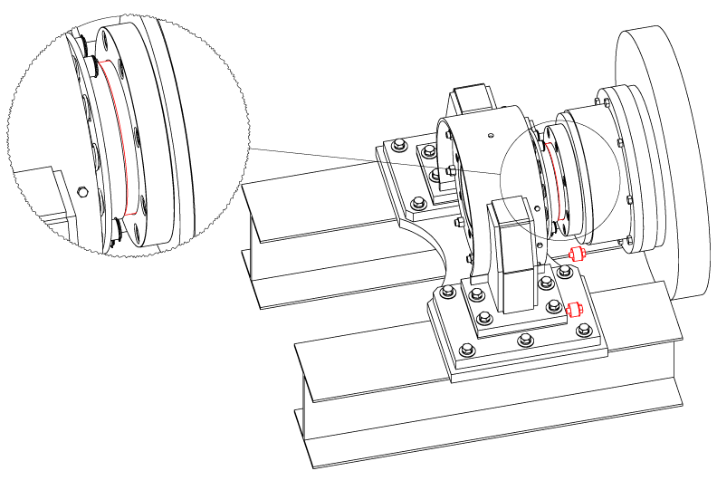
The endcap assembly is shipped compressed with two spacer assemblies (14B, 14C, and 14D). With assistance, slide the seal ring into place. Once installed, loosen the spacer assemblies.
Note: The bracket may have to be loosened in order to slide the seal ring into place.
Important: After installing the end cap assembly, check that the "X" dimension matches the Kadant Johnson drawing. If it is incorrect, please contact Kadant Johnson.

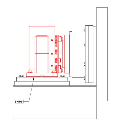
Check the alignment. The rotary joint should be within .040" (1.016 mm) plumb and square to the face of the journal. Axially, the seal ring should be centered on the nipple within .100" (2.54 mm).
Note: For new installations, the bracket may need to be shimmed for alignment. The bracket and mounting plates have slotted holes for adjustment.

Install the head using the gasket provided. Install the guard if it was previously removed.
IS-61050PT-1

