Read all of the instructions before proceeding.
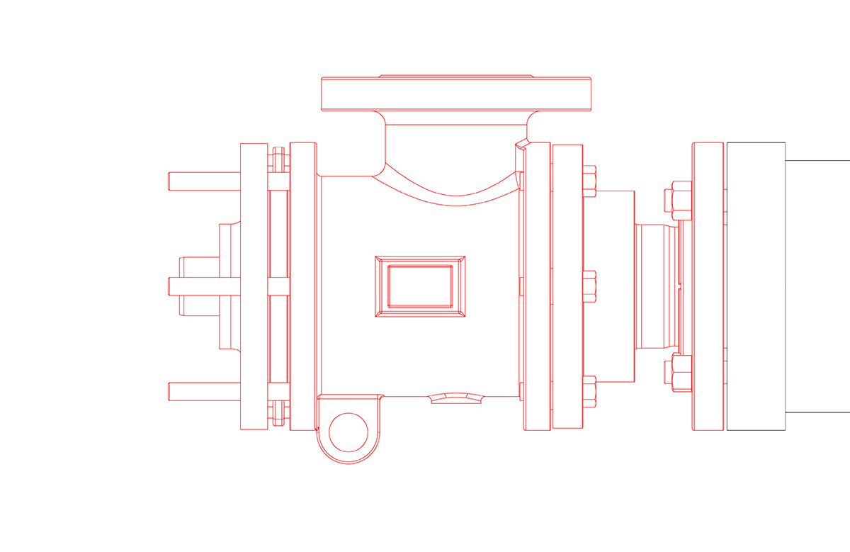
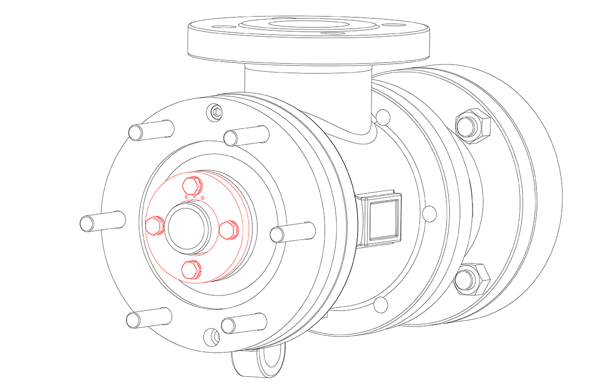
Refer to Kadant Johnson assembly drawing for part identification and to drawing A37640 for torque specifications. For easy identification, parts used in individual steps are often accompanied with their position in the assembly drawing [e.g. gasket (8B)]. Tighten all fasteners in a star pattern. Certified drawings are available upon request. Dimensions are for reference only and subject to change.
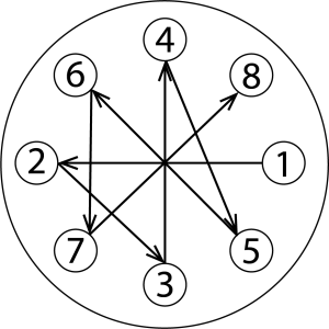

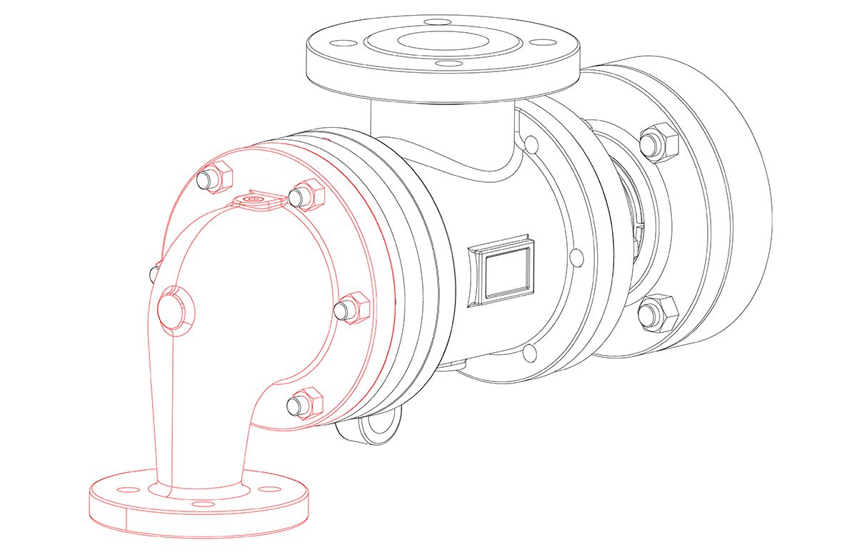
Disconnect the piping and anti-rotation device. Remove the head.

Important: Mark the end of the horizontal pipe where it passes through the pressure plate or measure and record the distance it is protruding out. Refer to either during installation.
Note: In some instances a horizontal pipe handling tool will be needed. Contact Kadant Johnson if one is needed.
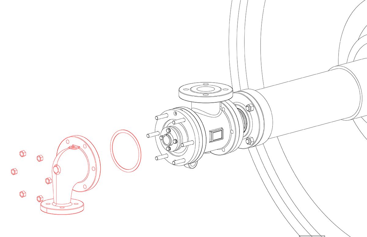
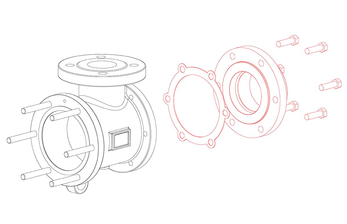
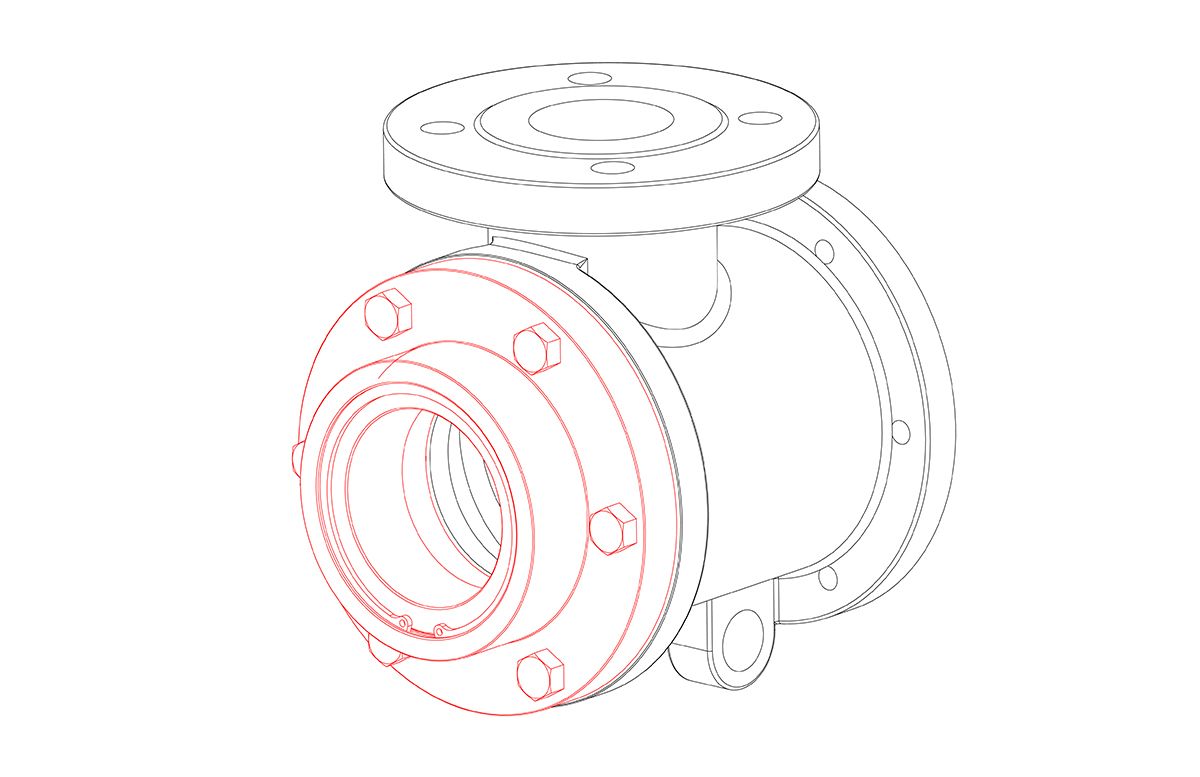
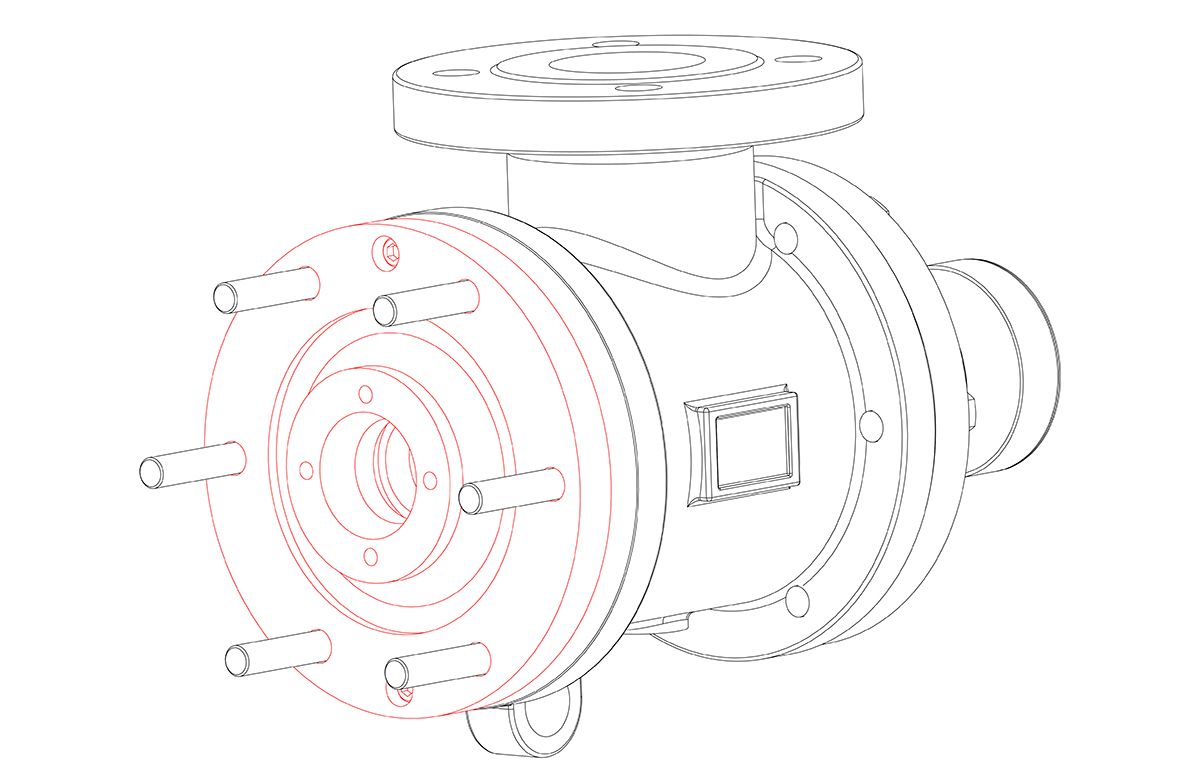
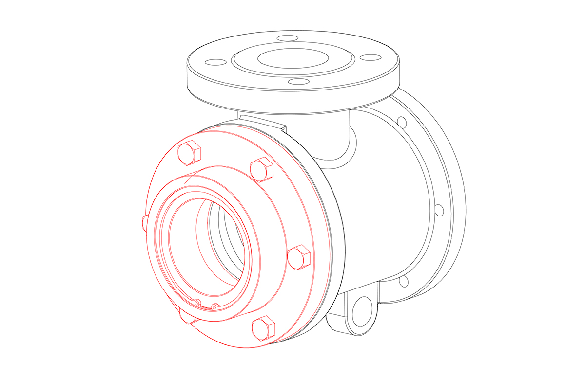
Loosen and remove the nipple flange and slide the rotary joint away from the journal. Remove the metal gasket (8Q) from the journal flange and discard. Remove the split wedges and nipple flange and save for reuse.

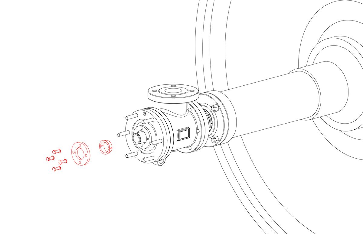
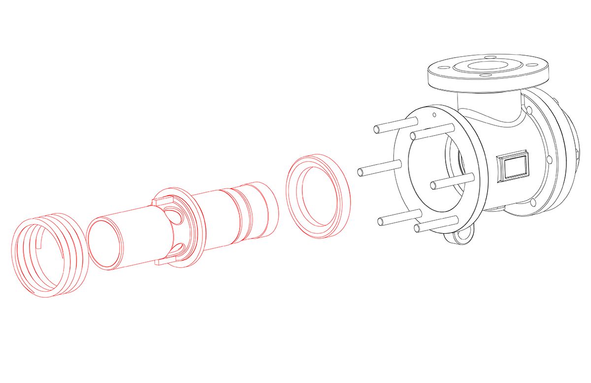
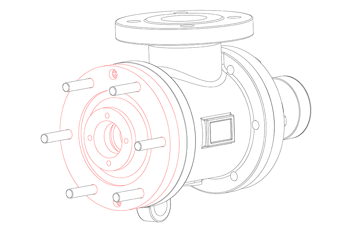
Remove the wedge plate and assembly plate by loosening the two cap screws (31A).
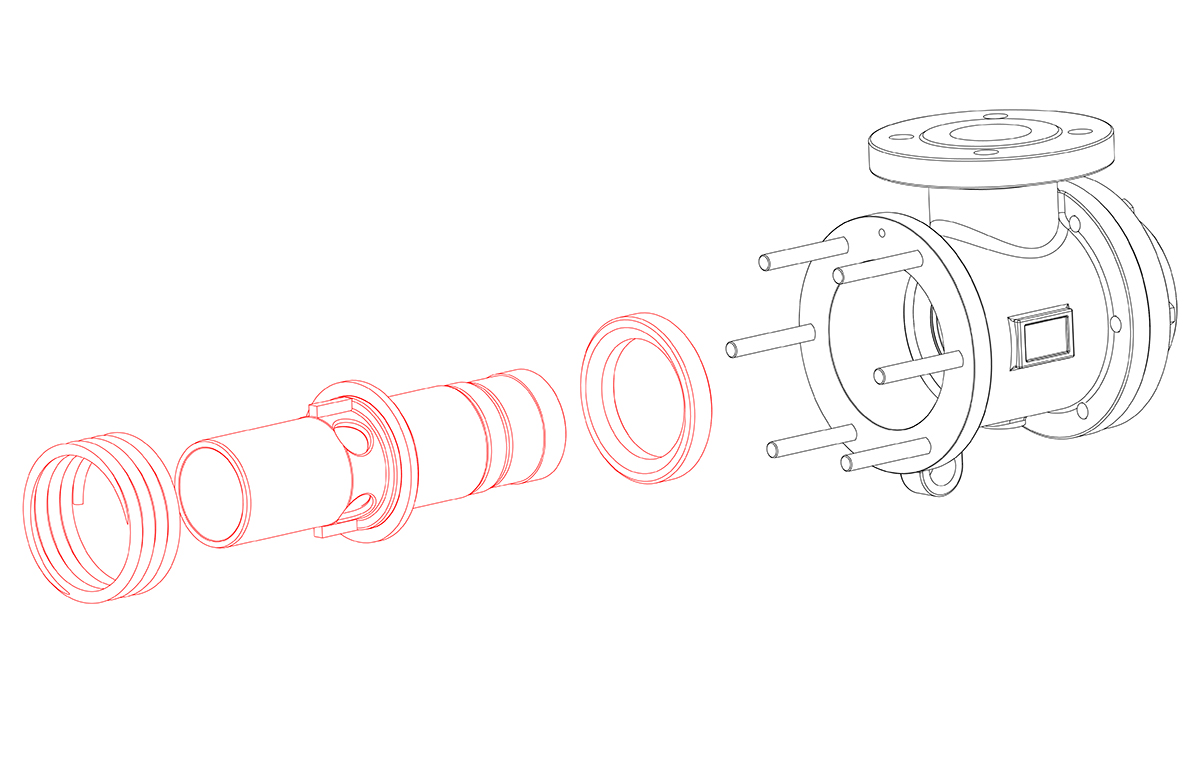
Remove the front guide and assembly consisting of the nipple, spring shoulder, spring, and seal ring.
Note: The spring shoulder may be stuck on the nipple. Separate the two parts.
Note: ELS rotary joints that are 3 1/2" and larger, the front guide is contained in the assembly plate and is removed with it.
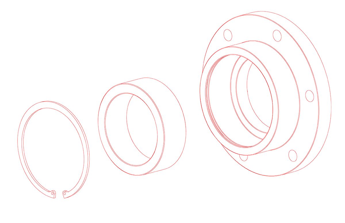
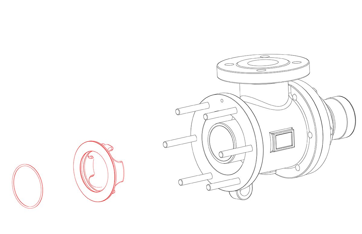
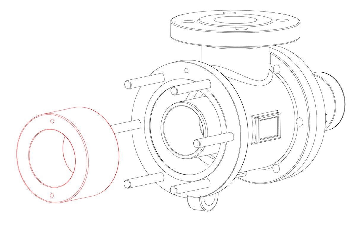
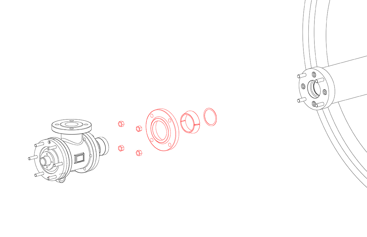
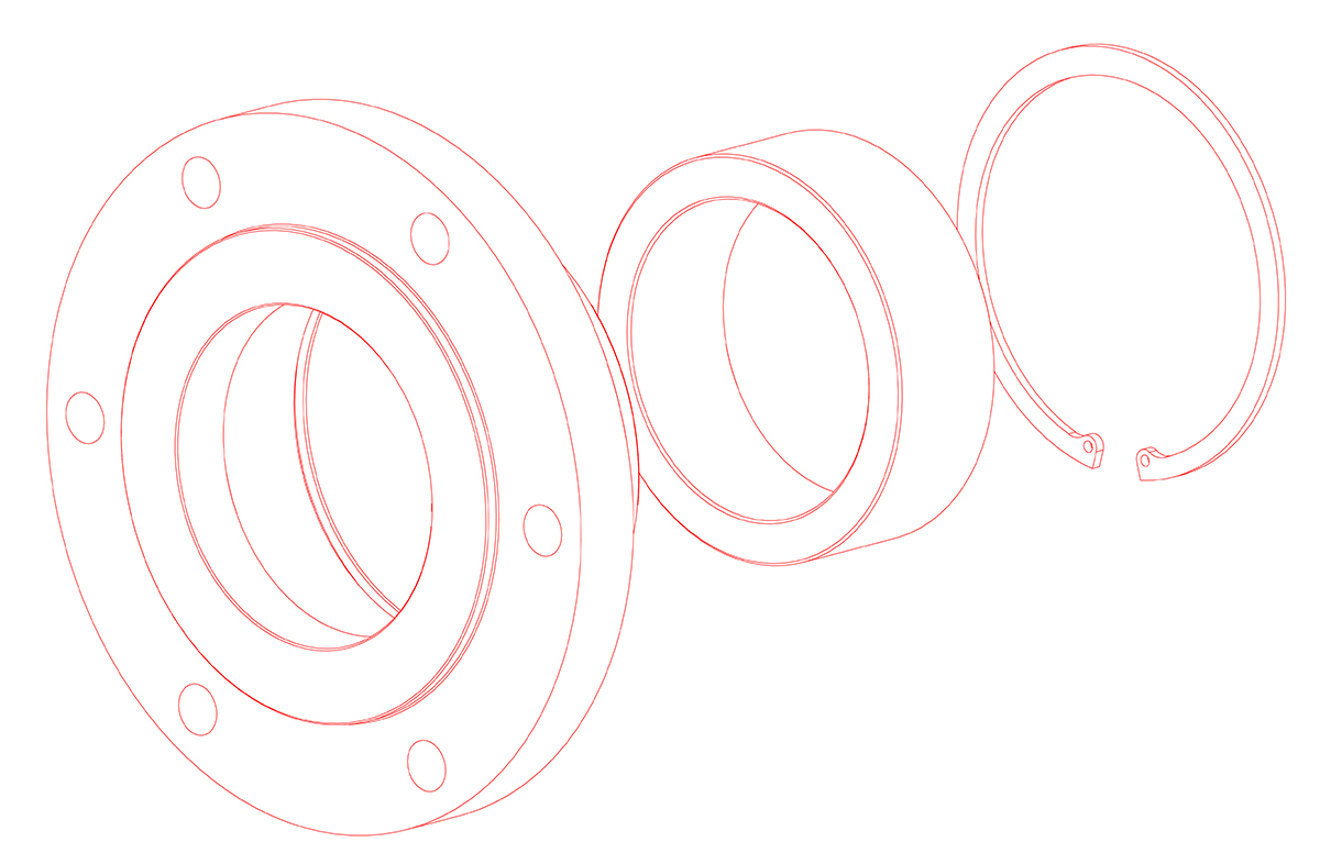
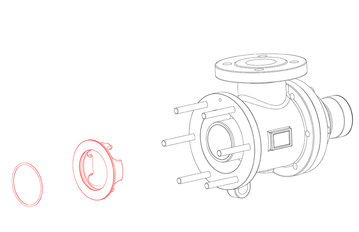
Separate the wear plate from the body. Remove the back guide by removing the retaining ring.

Install a new back guide into the wear plate and secure with the retaining ring. Using a new gasket, install the wear plate on the body.
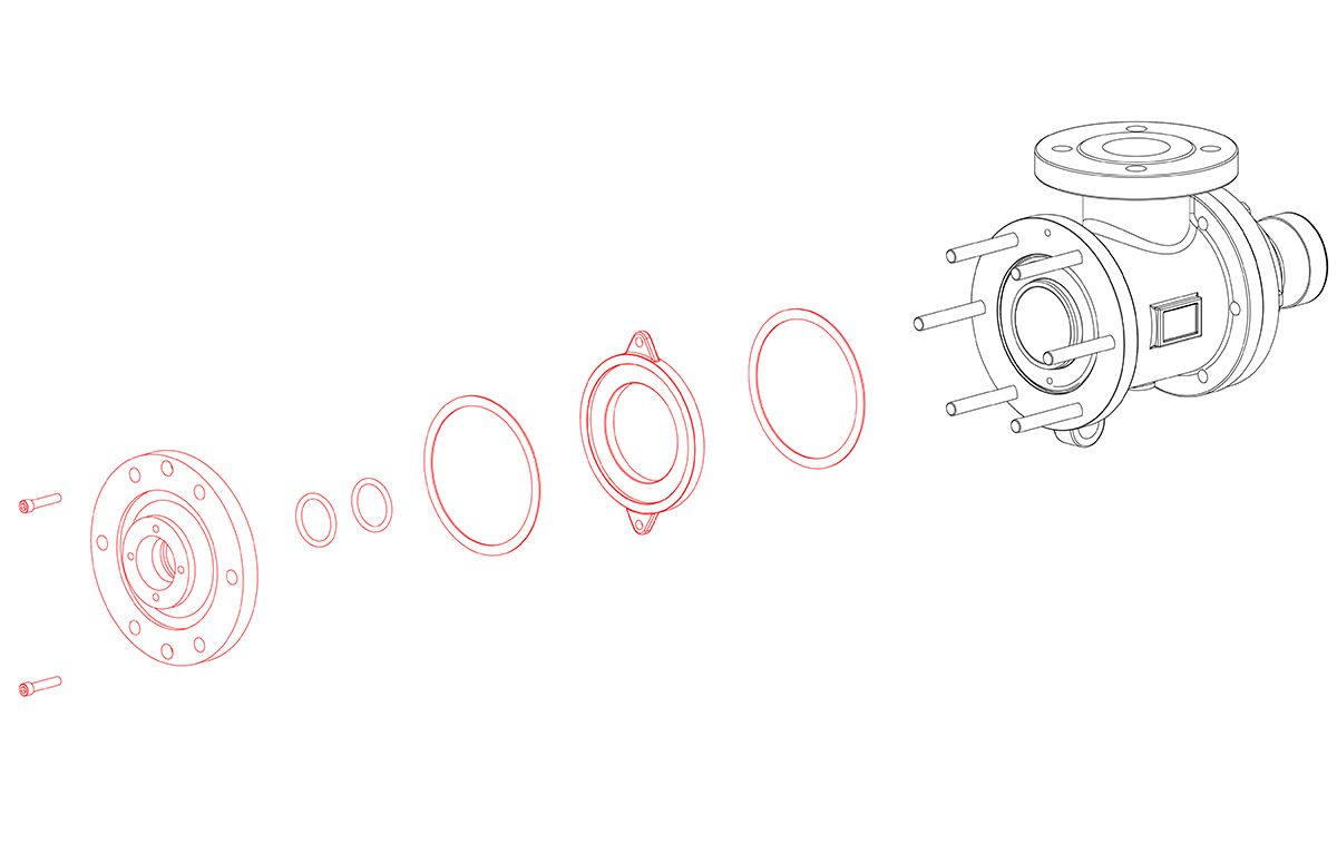
Turn the rotary joint upright and install a new seal ring, with the concave side facing outward. Install the nipple into the body followed by the spring.
Install a new O-ring into the spring shoulder. Install over the nipple by aligning the keys with the spring shoulder keyways.
Install the front guide over the nipple with the two pin holes facing outward.
Install a new O-ring into the assembly plate and two new O-rings into the wedge plate. Using two new gaskets, install the assembly plate and wedge plate while lining up the pins with the corresponding holes in the guide.
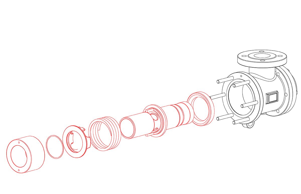
Slide the nipple flange over the rotary joint nipple with the taper facing out. Place the split wedges into the recess of the nipple. Slide the nipple flange over the wedges.

Place metal gasket into the journal flange. Lift the rotary joint up, slide over the horizontal pipe and into the journal flange. Secure to studs with nuts. An even gap of 1/8" to 3/16" (3 to 5 mm) should remain in between the journal flange and nipple flange.

Place the split rings into the wedge plate. Install the pressure plate over the split rings and hand tighten. Position the horizontal pipe as it was in step 2. Tighten cap screws evenly to 8 ft-lbs (11 Nm). Tap the pressure plate with a soft-faced hammer to seat the split wedges. Tighten cap screws evenly to 16 ft-lbs (22 Nm).

Install the head using a new gasket. Reinstall the piping and anti-rotation device.
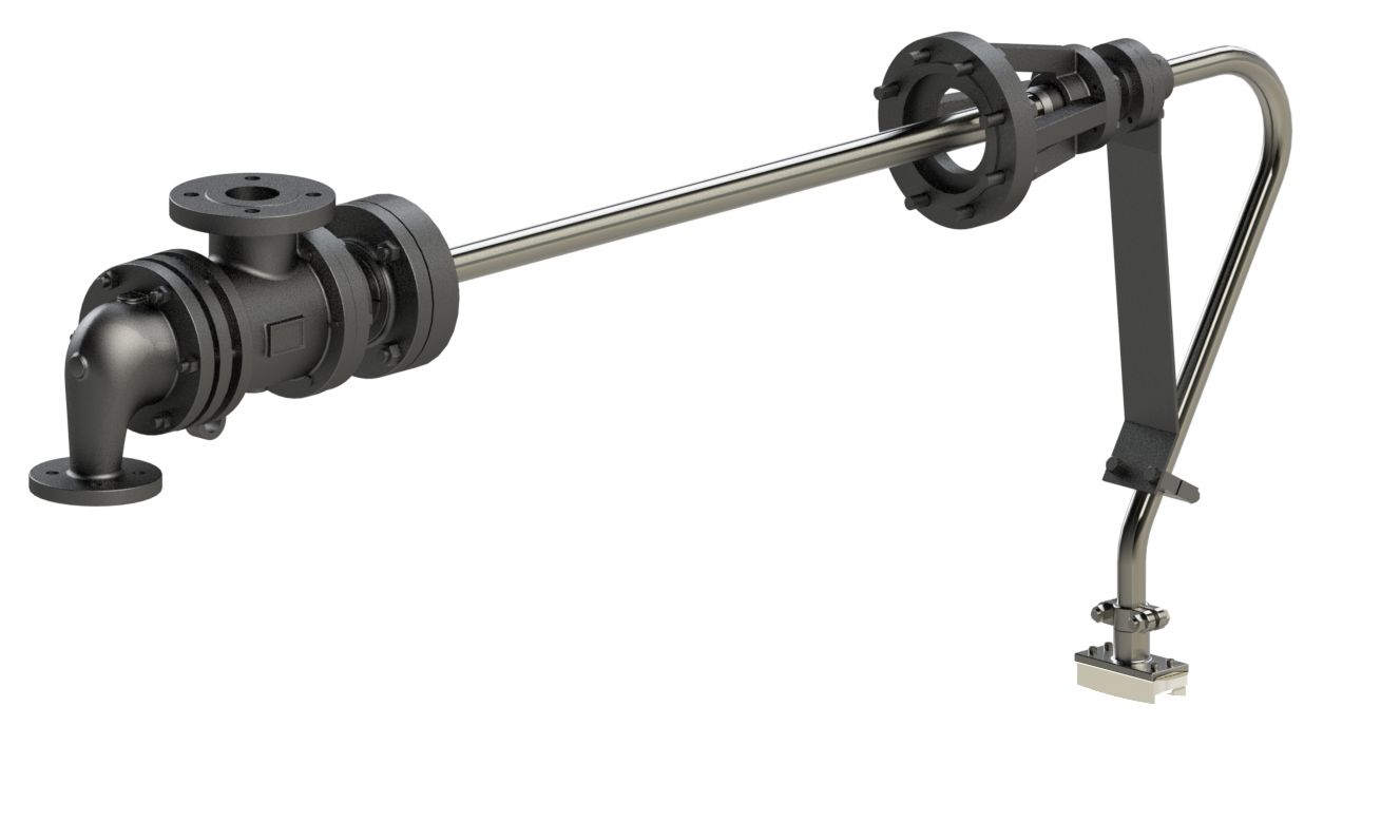
R-ELSJ-ISSS-SYPHON

