Read all of the instructions before proceeding.
Refer to Kadant Johnson assembly drawing for part identification and to drawing A37640 for torque specifications. For easy identification, parts used in individual steps are often accompanied with their position in the assembly drawing [e.g. gasket (8B)]. Tighten all fasteners in a star pattern. Certified drawings are available upon request. Dimensions are for reference only and subject to change.

Remove existing equipment. Clean journal gasket surface. Chase and clean all tapped holes.

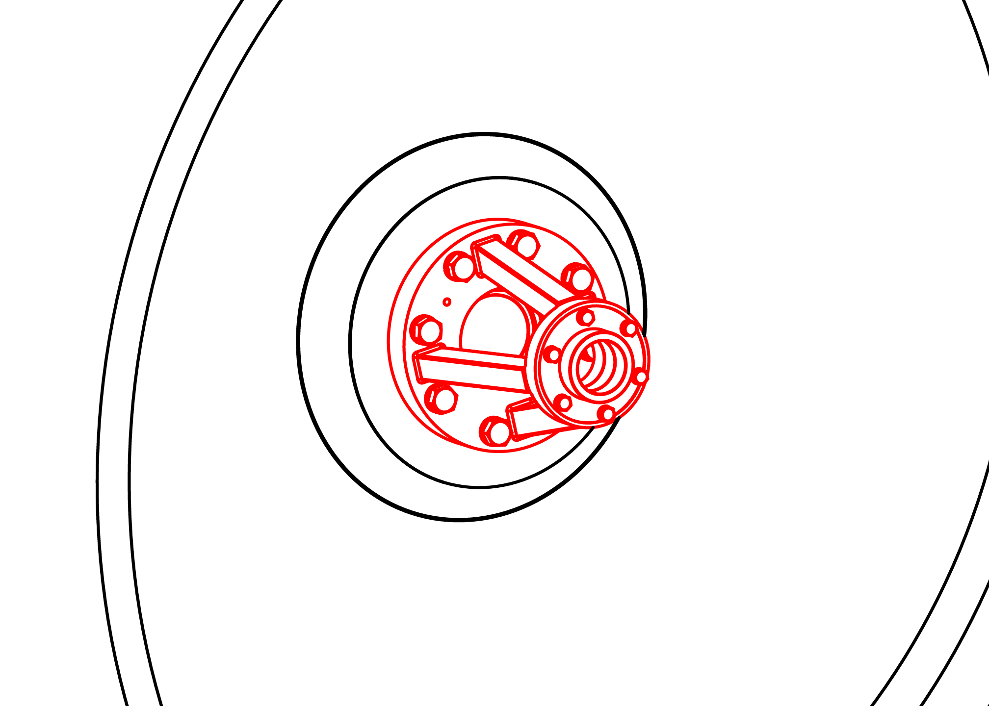
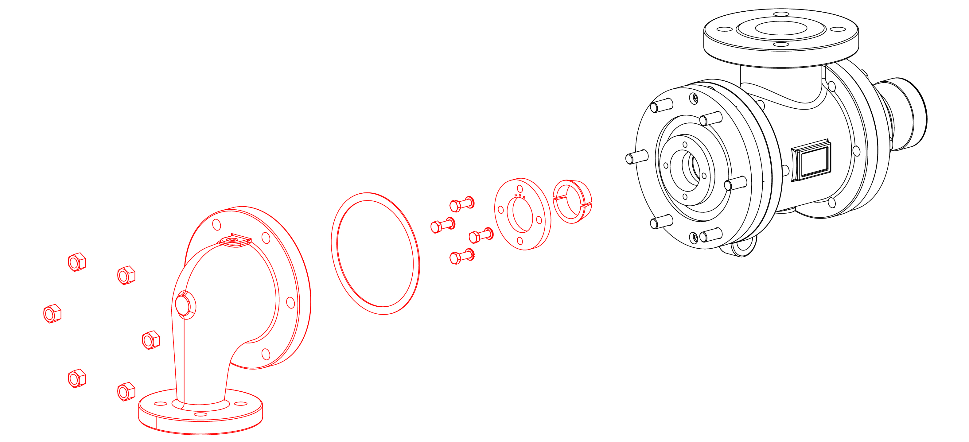
Install the journal flange with a new gasket.
Assemble the internal spider by inserting two guides. Install the third into the bushing retaining plate. Mount the retaining plate to the end of the spider using the cap screws provided.
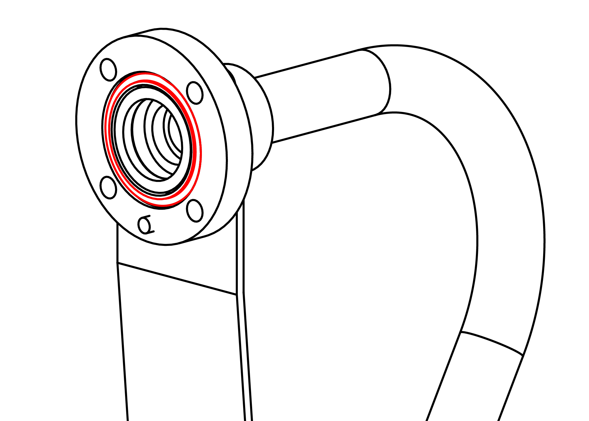
NOTE: If using an insulating sleeve, attach it to the spider with the cap screws provided. Install the O-rings into the journal flange.
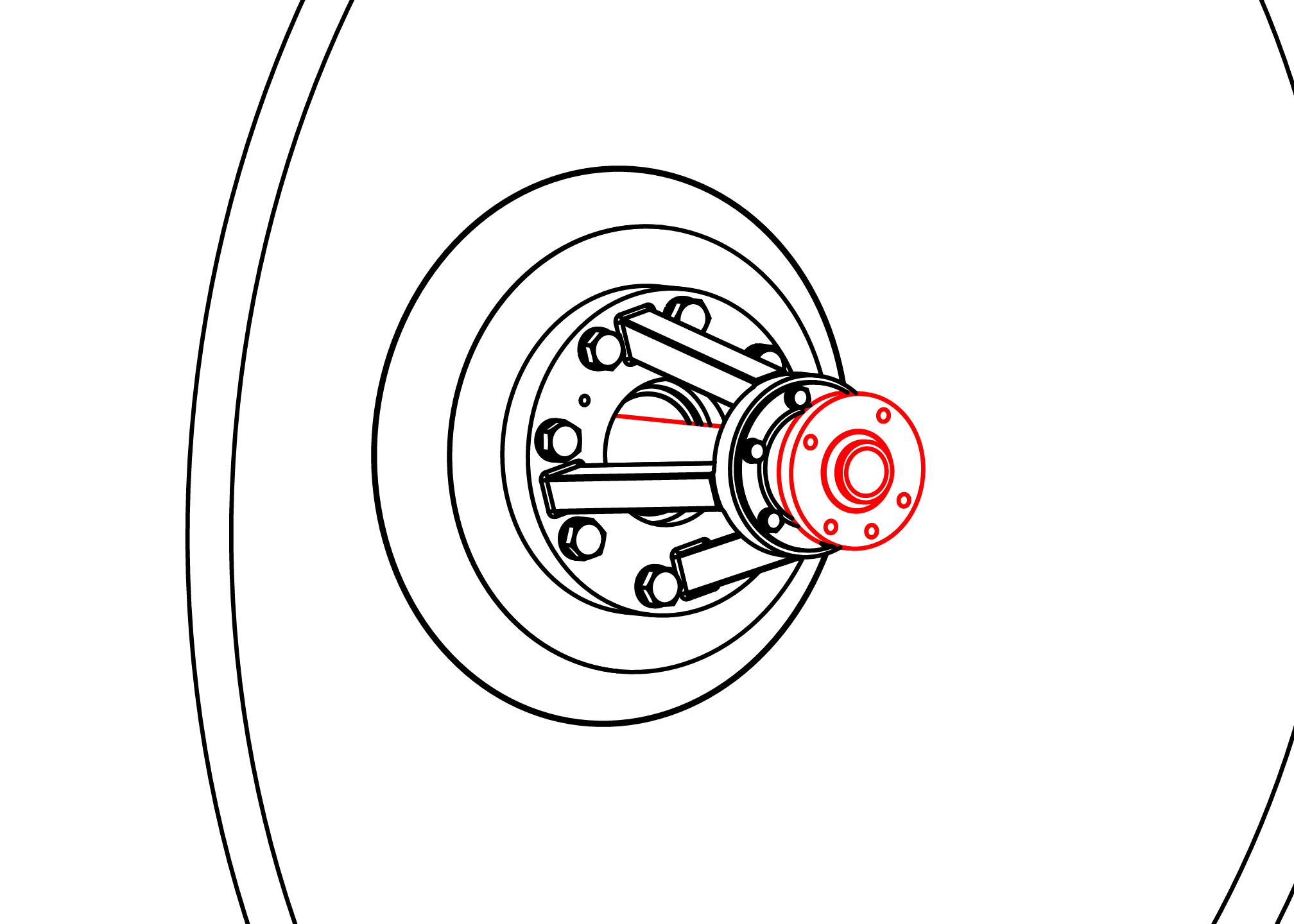
Inside the dryer, install the internal spider using the gasket provided.

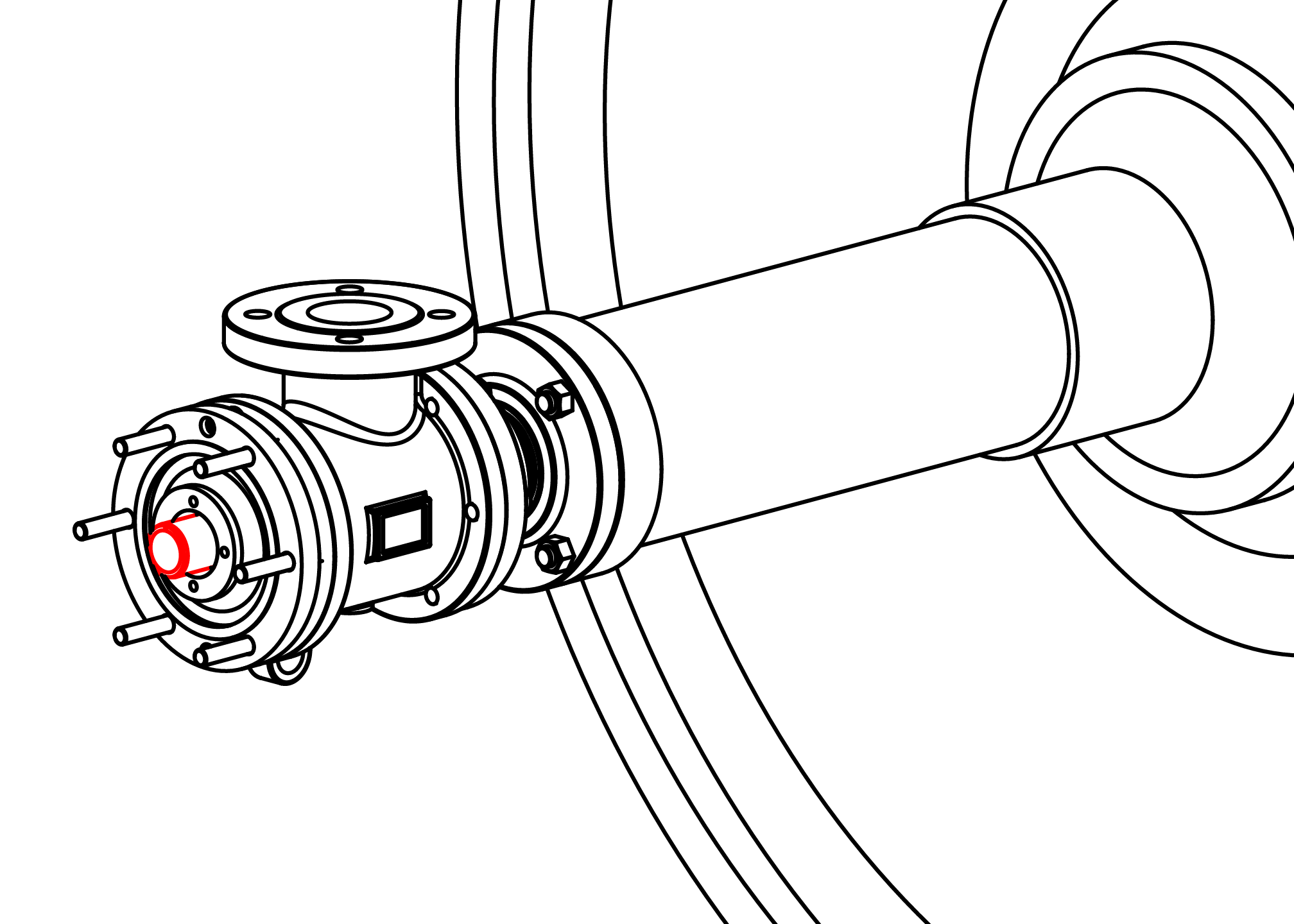
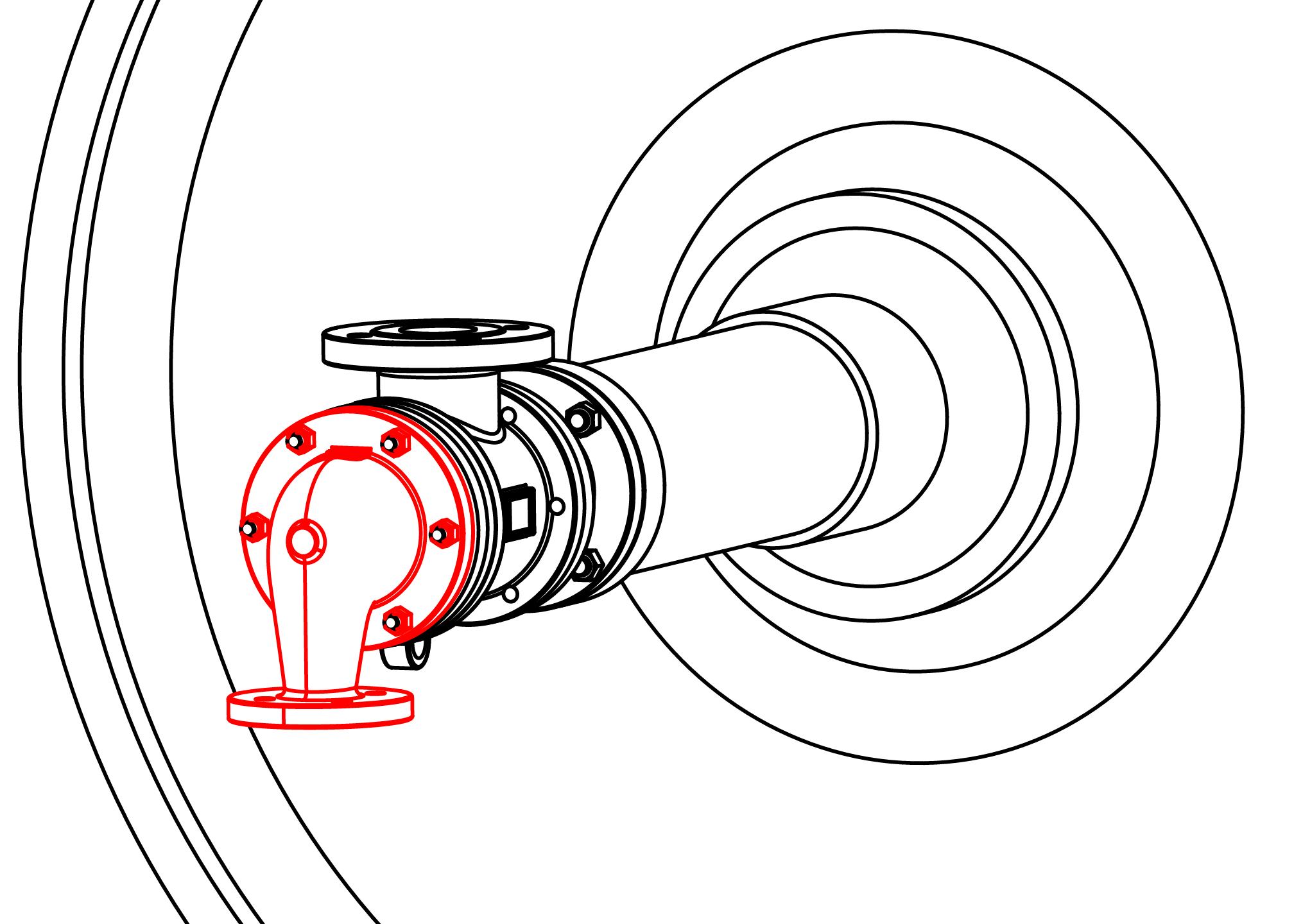
Remove the head and head gasket. Remove the cap screws, lock washers, pressure plate, and split wedges from the wedge plate. Set all parts aside for reuse.
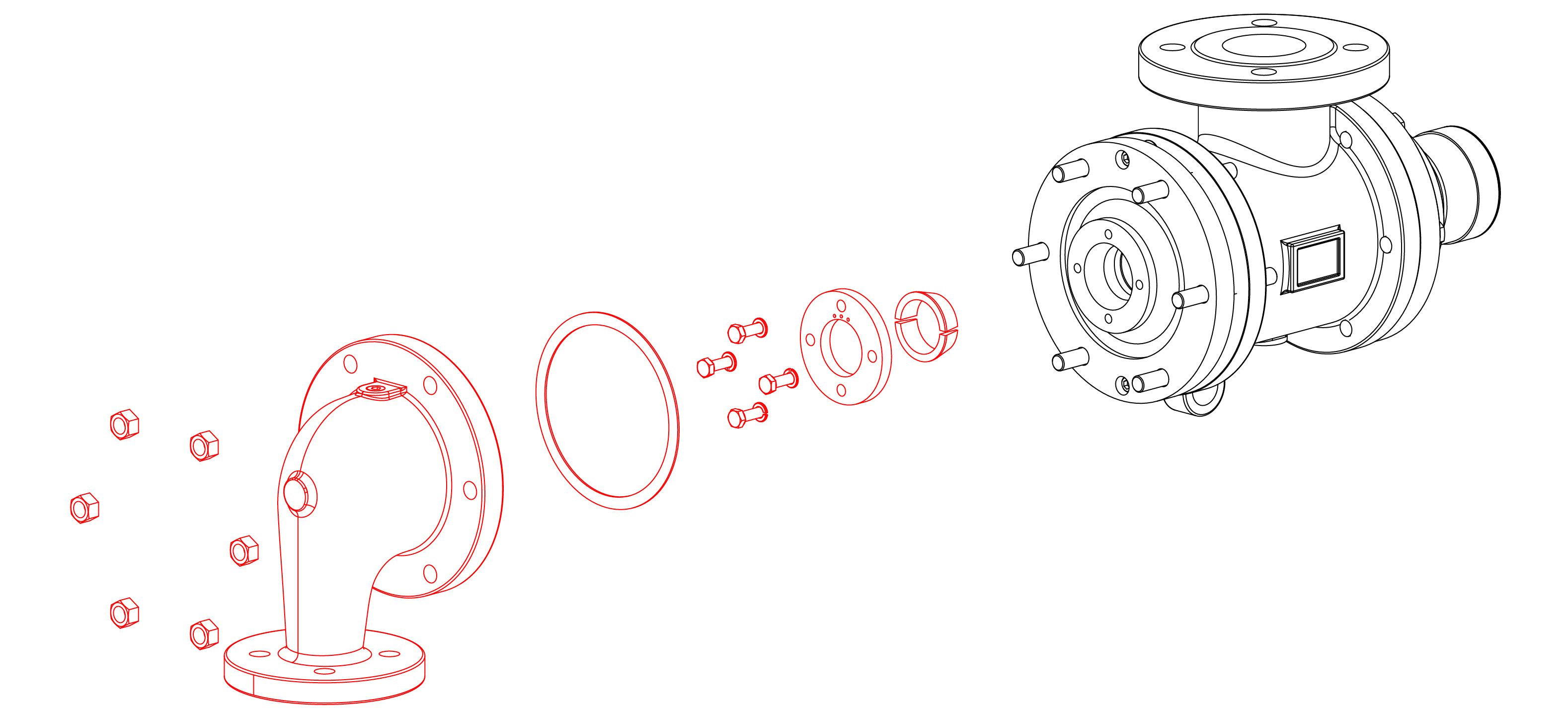
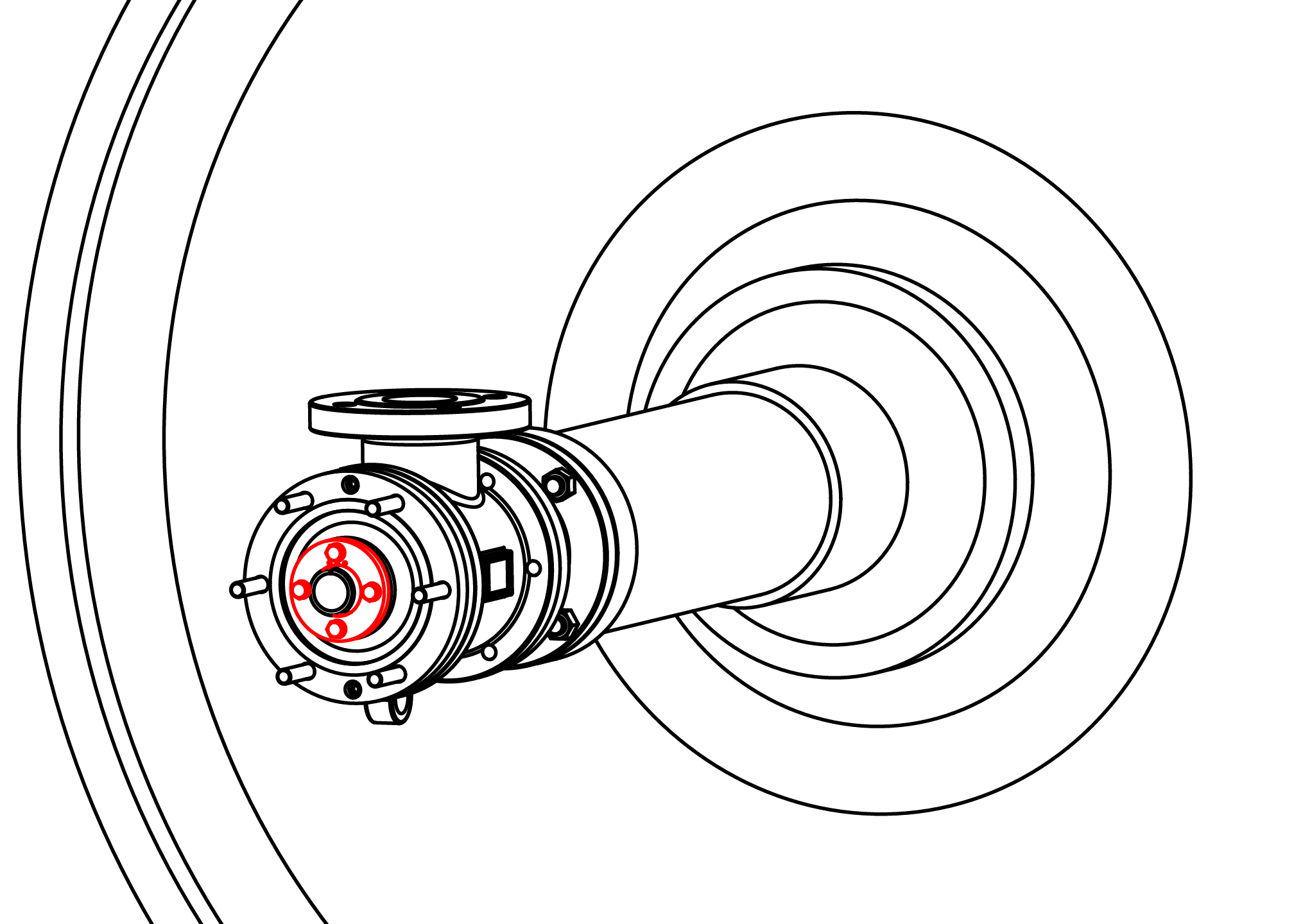
Slide the nipple flange over the rotary joint nipple with the taper facing out. Place the split wedges into the recess of the nipple. Slide the nipple flange over the wedges.
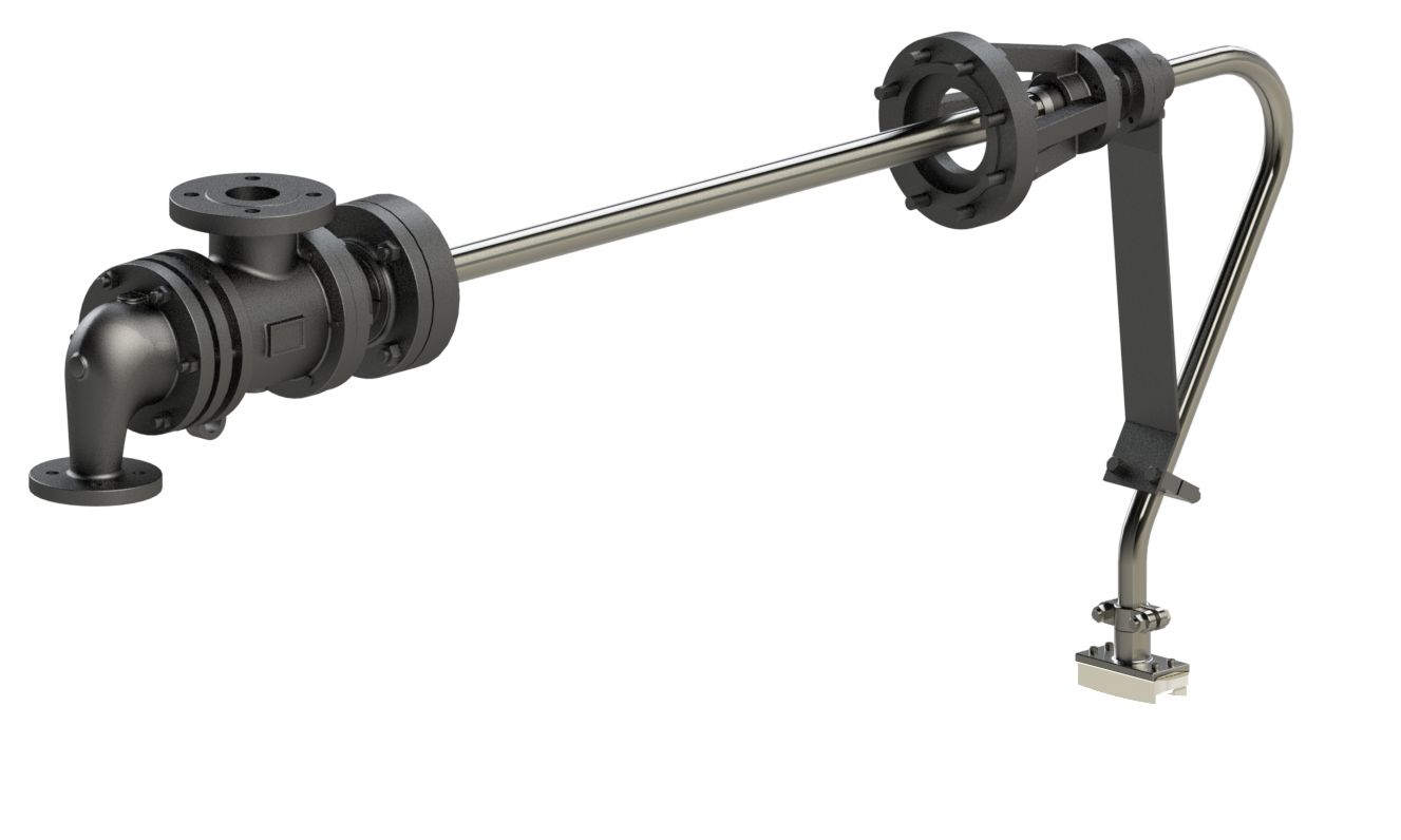
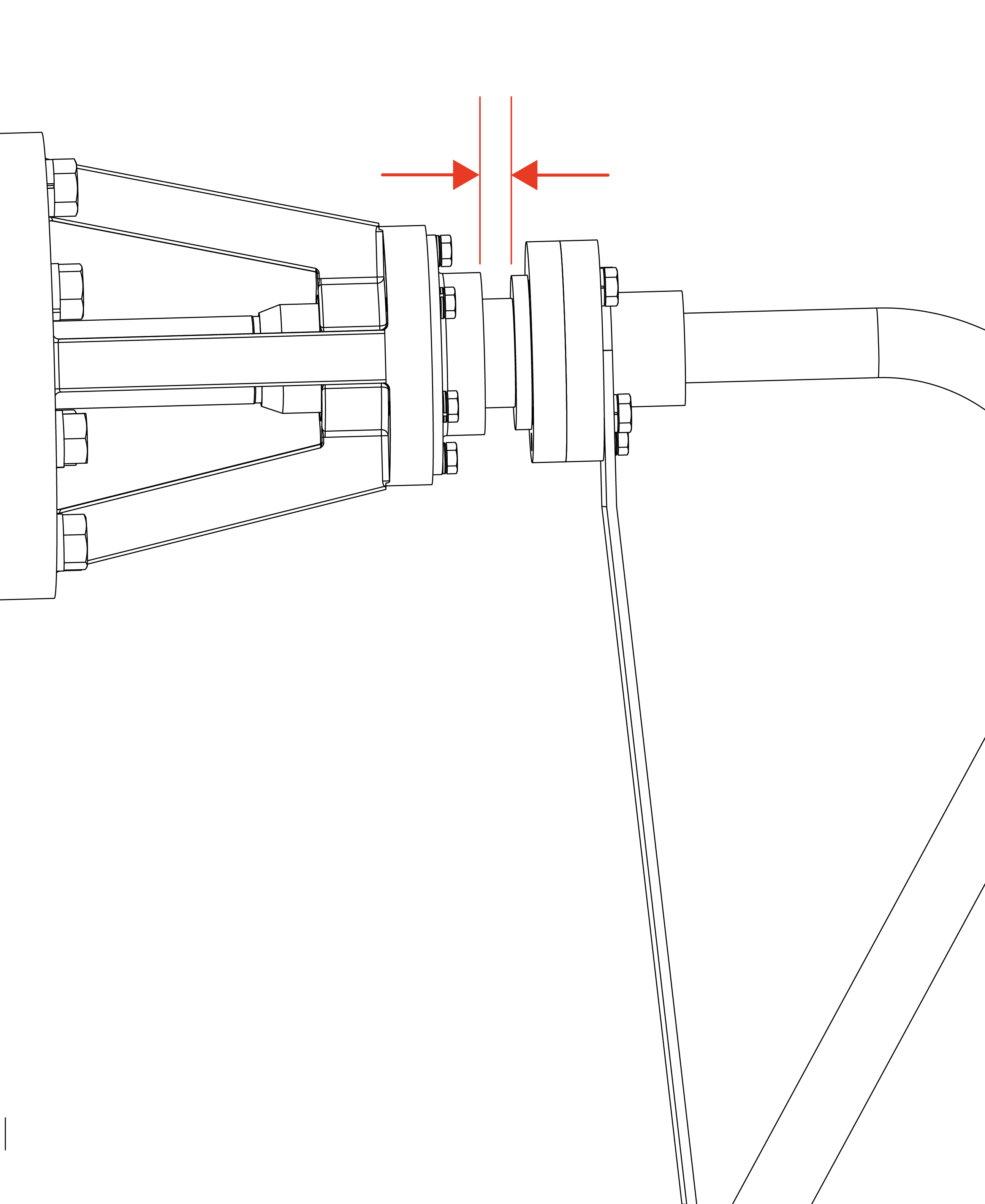
Place metal gasket into the journal flange. Install the rotary joint by inserting the nipple into the journal flange and securing the studs with nuts. An even gap of 1/8" to 3/16" (3 to 5 mm) should remain in between the journal flange and nipple flange.
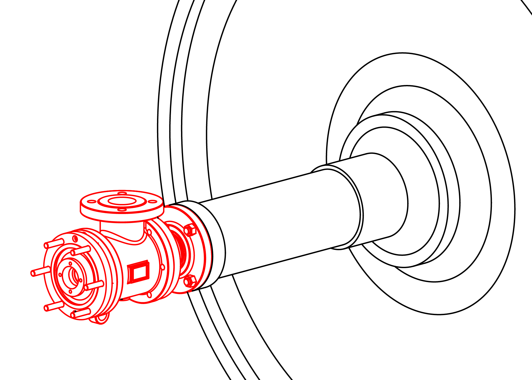
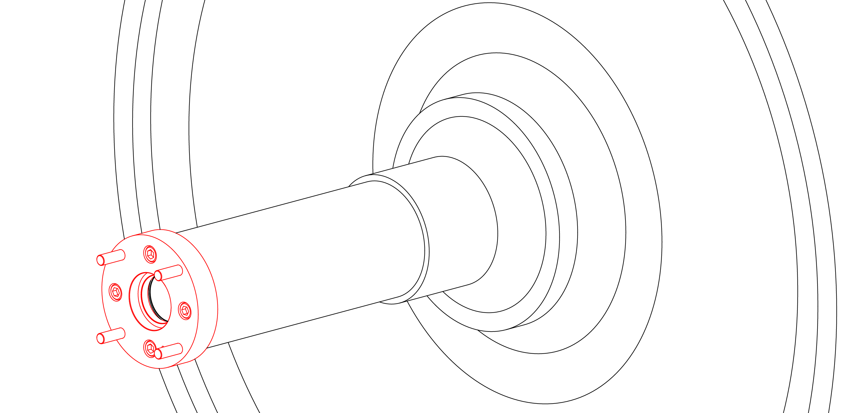
Carefully install the horizontal pipe by passing it through the guides of the spider. Continue to slide the pipe through the journal and into the rotary joint until it passes through the wedge plate.
Important: Ensure that the indexing mark on the non-flanged end is installed at the 12 o'clock position.

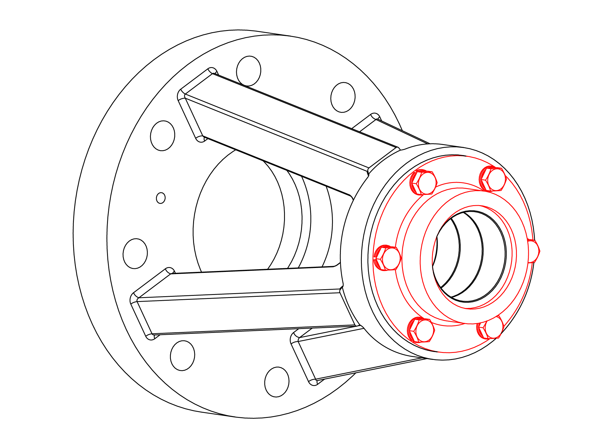
Lubricate and install the O-ring into the flange of the vertical pipe. Position the vertical pipe flange against the horizontal pipe flange and secure with fasteners provided.

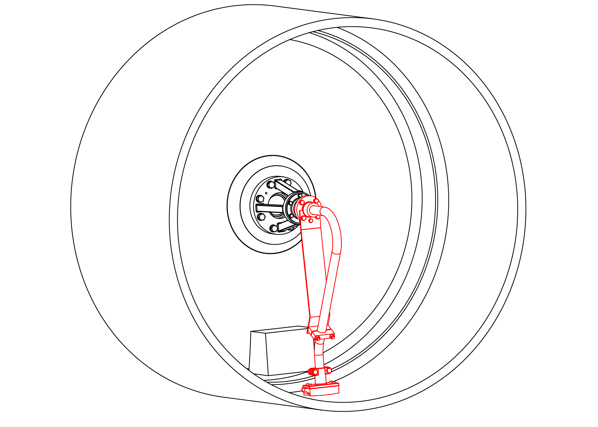
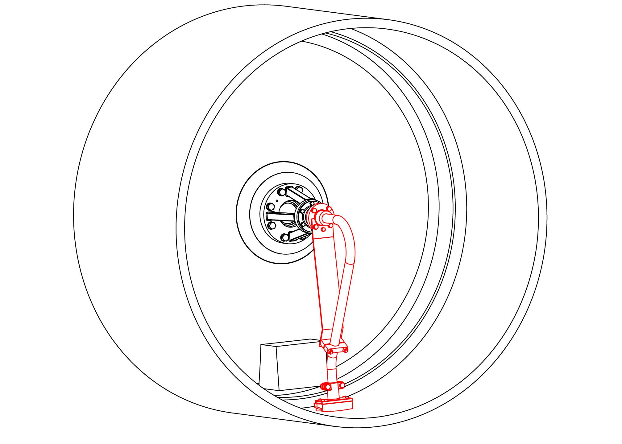
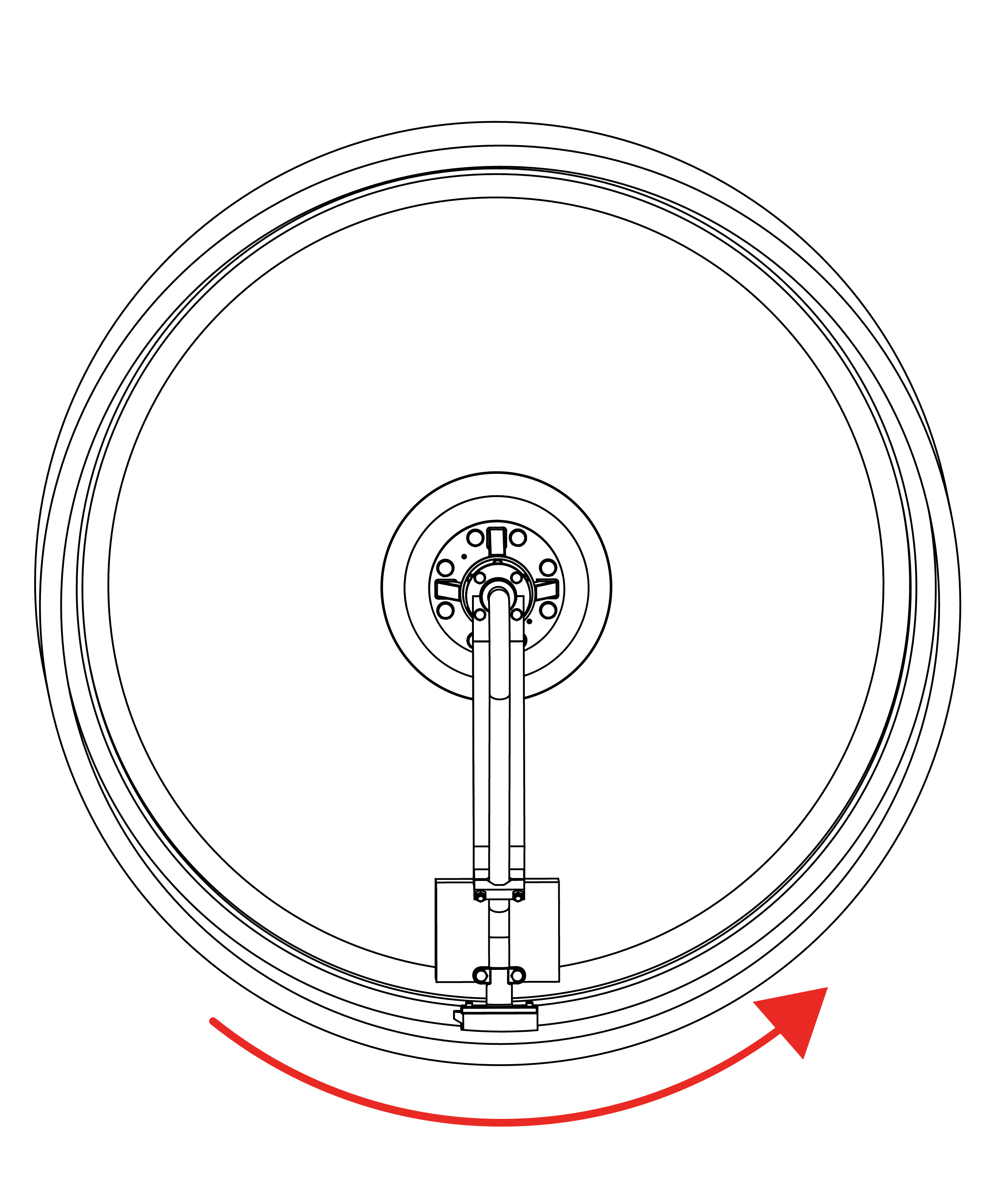
Check support bracket is vertical and syphon pick-up fitting is at the bottom of the dryer pointed into the rotation of the dryer. Set the pick-up fitting clearance per Kadant Johnson specifications using a gauge. Set the gap between retaining ring and horizontal pipe flange to a minimum of 0.059" (15 mm).


Install the split wedges and pressure plate into the wedge plate and secure with lock washers and cap screws. Tighten evenly to 8 ft-lbs (11 Nm). Tap the plate with a soft face hammer to seat the split wedges. Tighten to 16 ft-lbs (22 Nm).
Important: The indexing mark on the horizontal pipe should line up with a dimple on the pressure plate.
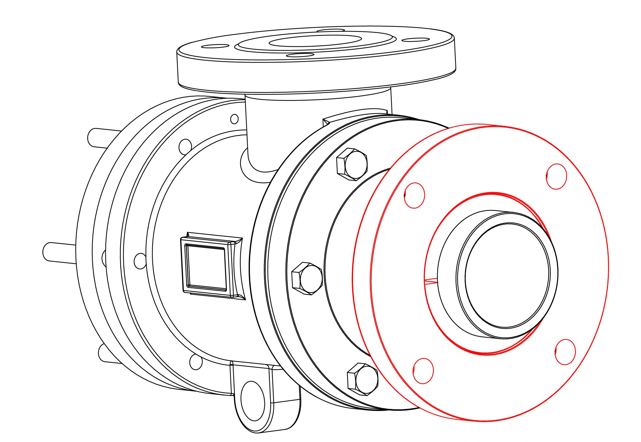
Install the head with the gasket provided.

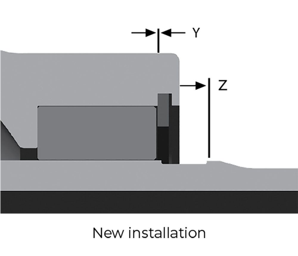
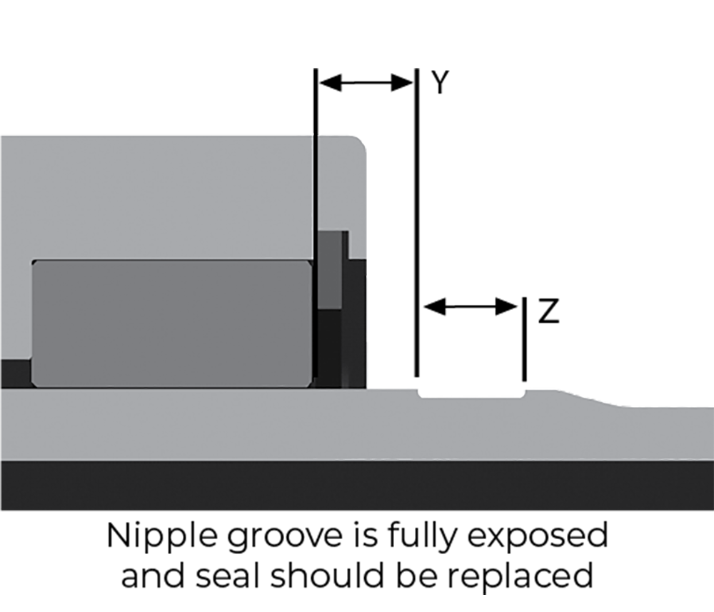
As the seal ring wears, the shoulder on the nipple will become exposed. When the shoulder is past the wear plate, equaling the maximum seal wear dimension, it is time to replace the rotary joint. Seal wear may also be measured using the "X" dimension. Refer to "Measuring Seal Ring Wear."
IS-ELSJ-ISSS-SYPHON

