
Installation Instructions for the 2800 and 2950 ELSJ

Effective: August 1, 2023

Introduction

Read all of the instructions before proceeding.

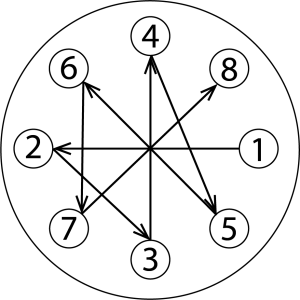
Refer to Kadant Johnson assembly drawing for part identification and to drawing A37640 for torque specifications. For easy identification, parts used in individual steps are often accompanied with their position in the assembly drawing [e.g. gasket (8B)]. Tighten all fasteners in a star pattern. Certified drawings are available upon request. Dimensions are for reference only and subject to change.

Safety

warning symbol

This safety symbol alerts you to risk of death or injury if the instructions are not followed. In all steps, death or injury may result if the machine is not de-energized, depressurized, cooled, and stopped. Death or injury may occur if the product is operated with a fluid type or at a pressure, temperature, or speed that do not meet its specifications. Death or injury may occur if heavy parts and pinch hazards are not handled properly. Follow your company’s safety procedures.

Step 1

Remove all debris from inside the piping and roll.

symbol

Equipment must be cool and free of pressure.

Step 2

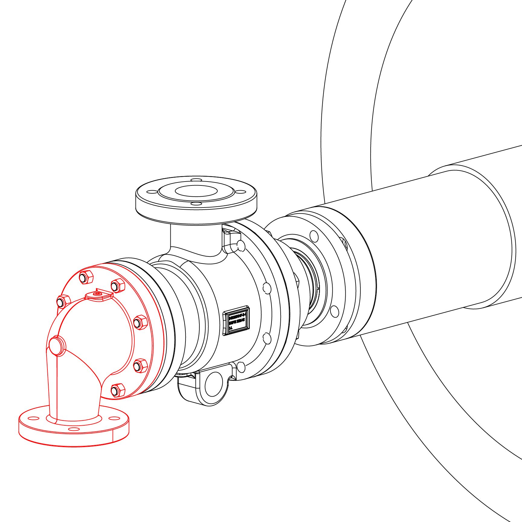
Remove the head and head gasket. Remove the cap screws, pressure plate, and split wedges from the wedge plate. Next, remove the cap screws, packing gland and packing. Set all parts aside for reuse.

Step 3

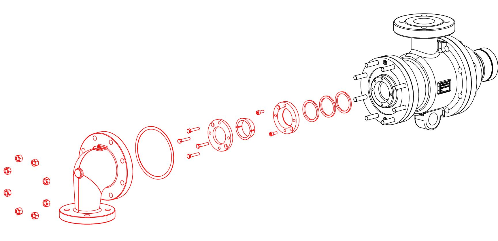
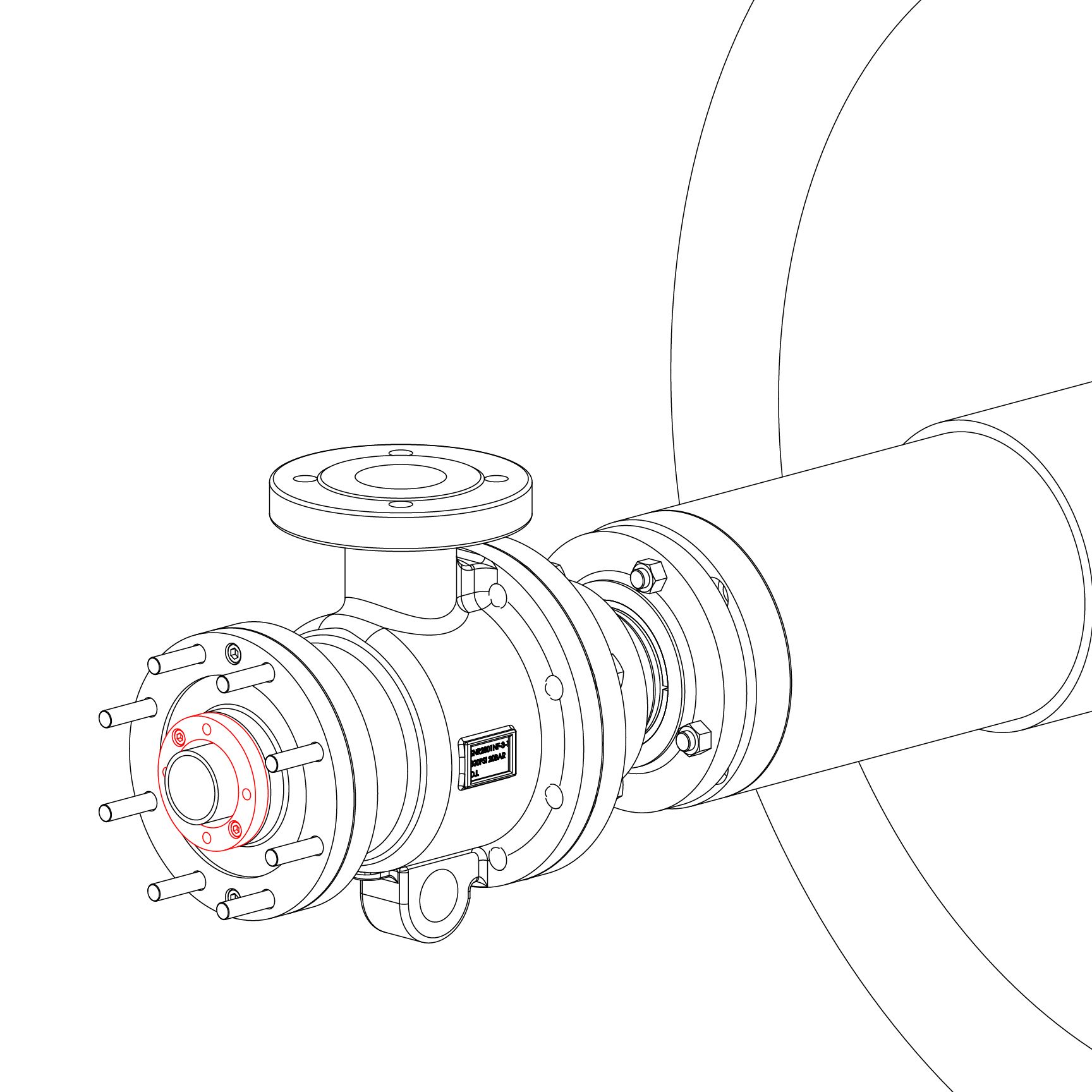
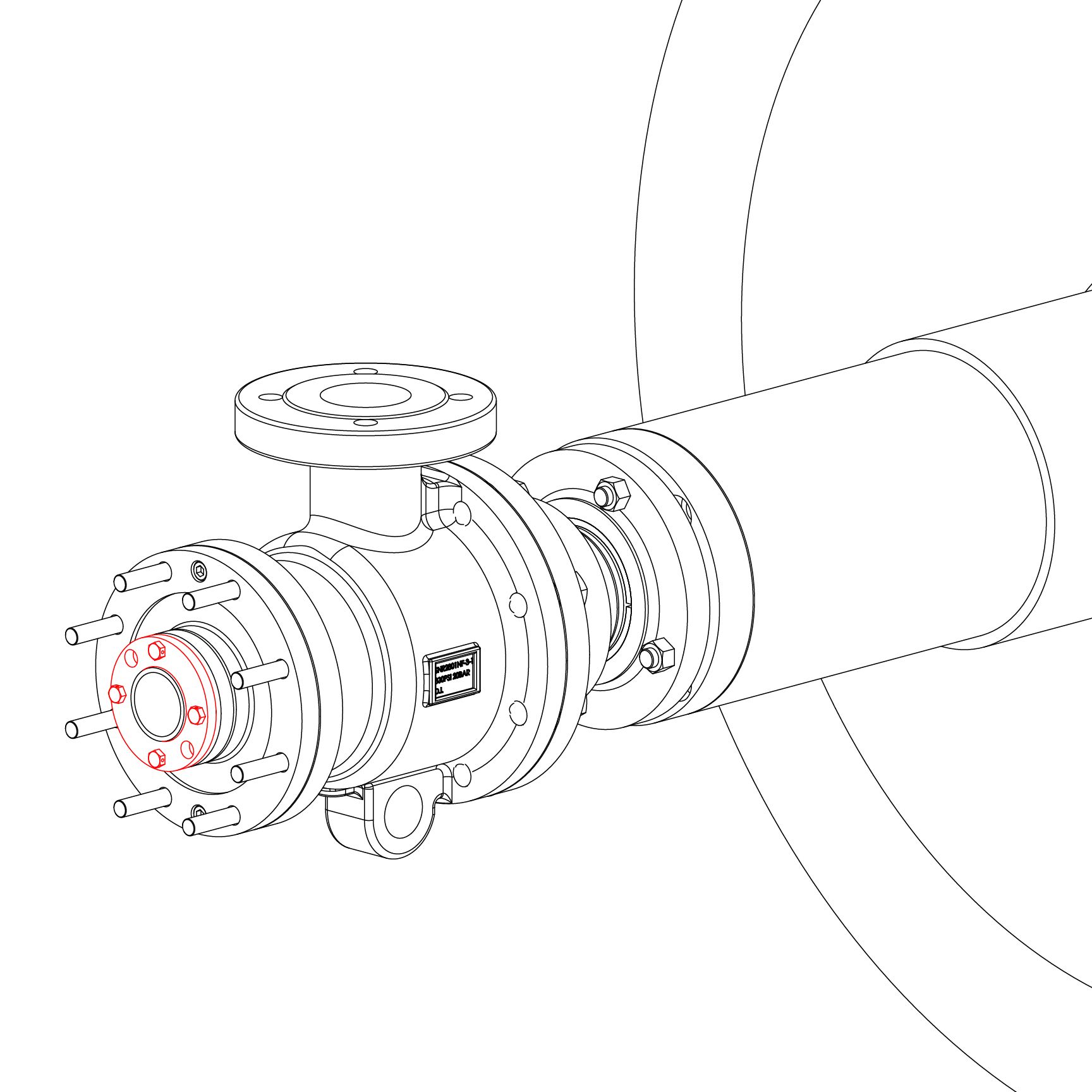
Slide the nipple flange over the rotary joint nipple with the taper facing out. Place the split wedges into the recess of the nipple. Slide the nipple flange over the wedges.

Step 4

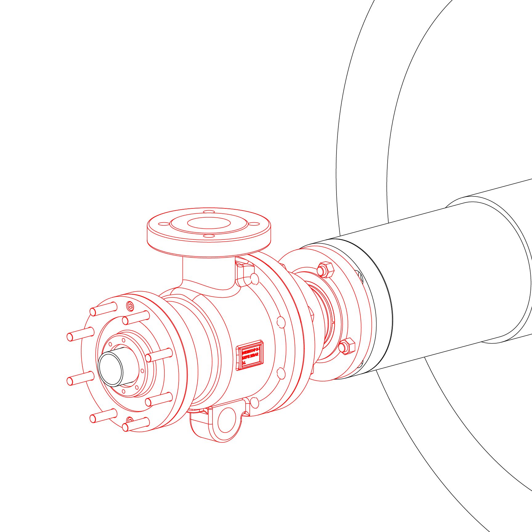
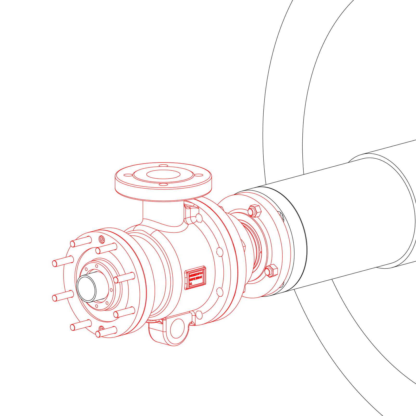
Place metal gasket into the journal flange. Install the rotary joint by inserting the nipple into the journal flange and securing the studs with nuts. An even gap of 1/8" to 3/16" (3 to 5 mm) should remain in between the journal flange and nipple flange.

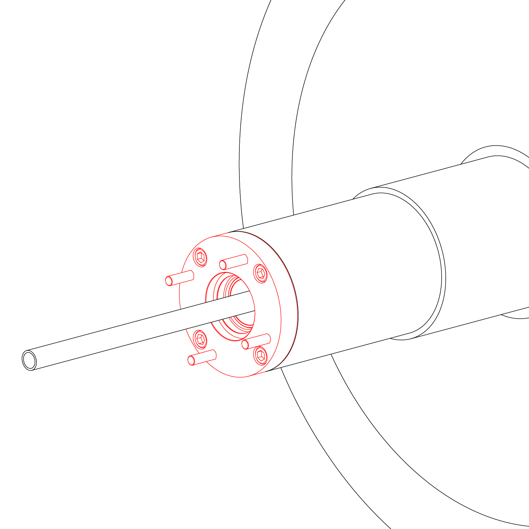
IMPORTANT: Make sure that the horizontal pipe extends 1" (25 mm) past the end of the assembly plate and is in the correct position inside the roll.

Step 5

Install packing (35) into the assembly plate and secure with the packing gland and cap screws. Tighten caps screws evenly to 15 ft-lbs (20 Nm).

Step 6

Place the split wedges (42) into the packing gland and secure with the pressure plate (43). Tighten the cap screws to 15 ft-lbs (20 Nm). Thread the safety wire through cap screws.

Step 7

Reinstall the head and gasket and secure with hex nuts.


IS-2800-2950-ELSJ

The Kadant Johnson Warranty
Kadant Johnson products are built to a high standard of quality. Performance is what you desire: that is what we provide. Kadant Johnson products are warranted against defects in materials and workmanship for a period of one year after the date of shipment. It is expressly understood and agreed that the limit of Kadant Johnson’s liability shall, at Kadant Johnson’s sole option, be the repair or resupply of a like quantity of non-defective product.

Kadant Johnson rotary joints and accessories could be subject to European Pressure Equipment Directive 2014/68/EU (PED). Modifications or changes to rotary joints and/or accessories are only permitted upon approval of Kadant Johnson. Only genuine Kadant parts and original accessories will ensure the safety of these assemblies. The use of other than original parts voids the warranty and will lead to forfeiture of the declaration of conformity and will invalidate any liability for damages cause thereby.