Effective: October 11, 2024

Read all of the instructions before proceeding.
Refer to Kadant Johnson assembly drawing for part identification and to drawing A37640 for torque specifications. For easy identification, parts used in individual steps are often accompanied with their position in the assembly drawing [e.g. gasket (8B)]. Tighten all fasteners in a star pattern. Certified drawings are available upon request. Dimensions are for reference only and subject to change.

This safety symbol alerts you to risk of death or injury if the instructions are not followed. In all steps, death or injury may result if the machine is not de-energized, depressurized, cooled, and stopped. Death or injury may occur if the product is operated with a fluid type or at a pressure, temperature, or speed that do not meet its specifications. Death or injury may occur if heavy parts and pinch hazards are not handled properly. Follow your company’s safety procedures.
Locate the mounting location of the SteamAssist bar and drill and tap the double facer side frames.
Note: In double wall applications, mount the SteamAssist bar underneath the upper single face web, coming off the upper glue station.
In heavyweight double wall applications, mount the additional SteamAssist bar under the lower single face web.

Equipment must be cool and free of pressure.
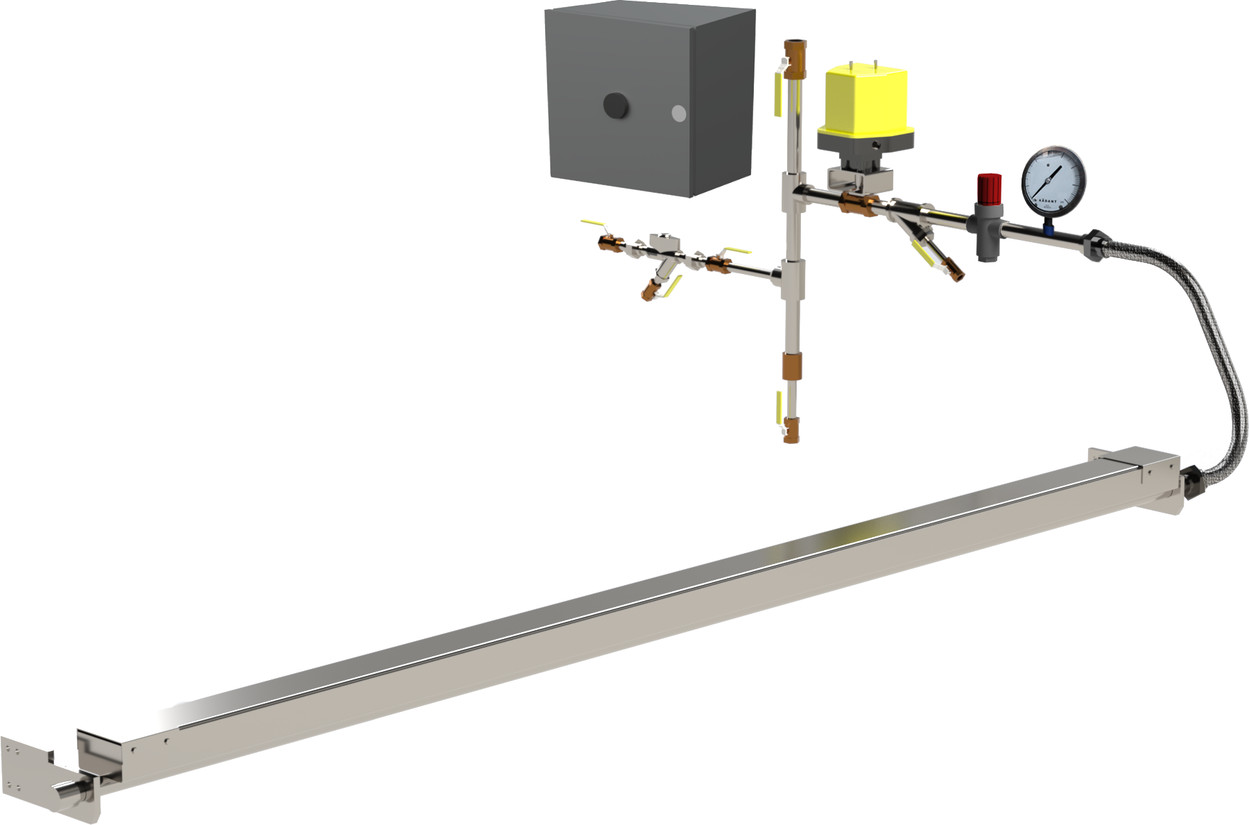
Mount the SteamAssist bar using the mounting brackets supplied with the bar(s).
Note: In some installations, addtional hardware may be needed to attach the bracket.
Adjust the surface of the SteamAssist bar to be 3/4" (up to 2") from the flute tips of the single facer.
Note: It's important that the flute tips are parallel with the bar for even heating.
Pipe the mechanical steam controls (supplied by Kadant Johnson) to the steam supply and to the SteamAssist bar.
Note: A 1” line coming from a suitable steam supply source (125 to 200 psi pressure) is required.
Install the control box in an easily accessible spot on the operator side of the machine. Ensure that all connections are tight and all local, state, and federal electrical codes have been met.
Note: If the automatic machine speed activation package is included, ensure the proper machine speed input is used.
Mount a small air pipe at the tip of the glue pan on the operator, pointed toward the drive side, to clear trapped steam and prevent glue from overheating.
Note: An electric fan may also be used.
Using a nail or wire less than 1/8", periodically remove dried and gelled starch buildup from the bar perforations.
Note: If steam exiting the bar is wetter than normal, the inside of the bar may also need to be cleaned. Remove the bar grate and clean.
If you have installation questions or comments to improve these instuctions, we are here to help! Fill out the form below or call 269-278-1715.
The Kadant Johnson Warranty
Kadant Johnson products are built to a high standard of quality. Performance is what you desire: that is what we provide. Kadant Johnson products are warranted against defects in materials and workmanship for a period of one year after the date of shipment. It is expressly understood and agreed that the limit of Kadant Johnson’s liability shall, at Kadant Johnson’s sole option, be the repair or resupply of a like quantity of non-defective product.
Kadant Johnson rotary joints and accessories could be subject to European Pressure Equipment Directive 2014/68/EU (PED). Modifications or changes to rotary joints and/or accessories are only permitted upon approval of Kadant Johnson. Only genuine Kadant parts and original accessories will ensure the safety of these assemblies. The use of other than original parts voids the warranty and will lead to forfeiture of the declaration of conformity and will invalidate any liability for damages cause thereby.