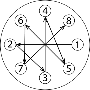
Viz výkres sestavy Kadant Johnson pro identifikaci dílů a výkres A37640 pro specifikace krouticího momentu. Pro snadnou identifikaci jsou díly použité v jednotlivých krocích často doprovázeny jejich polohou na montážním výkresu [např. těsnění (8B)]. Všechny upevňovací prvky utáhněte hvězdicově. Certifikované výkresy jsou k dispozici na vyžádání. Rozměry jsou pouze orientační a mohou se změnit.

Důležité: Některé aplikace znovu používají kryt ložiska a/nebo přírubu čepu. Pečlivě zkontrolujte svou žádost a přeskočte kroky, které neplatí.


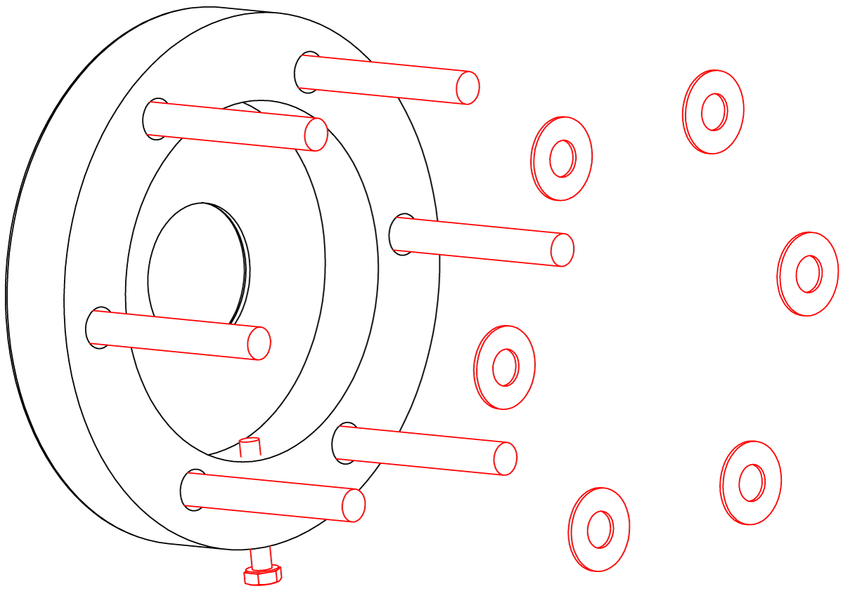
If using a bracket that is mounted to the machine face, install the bracket using the appropriate fasteners.
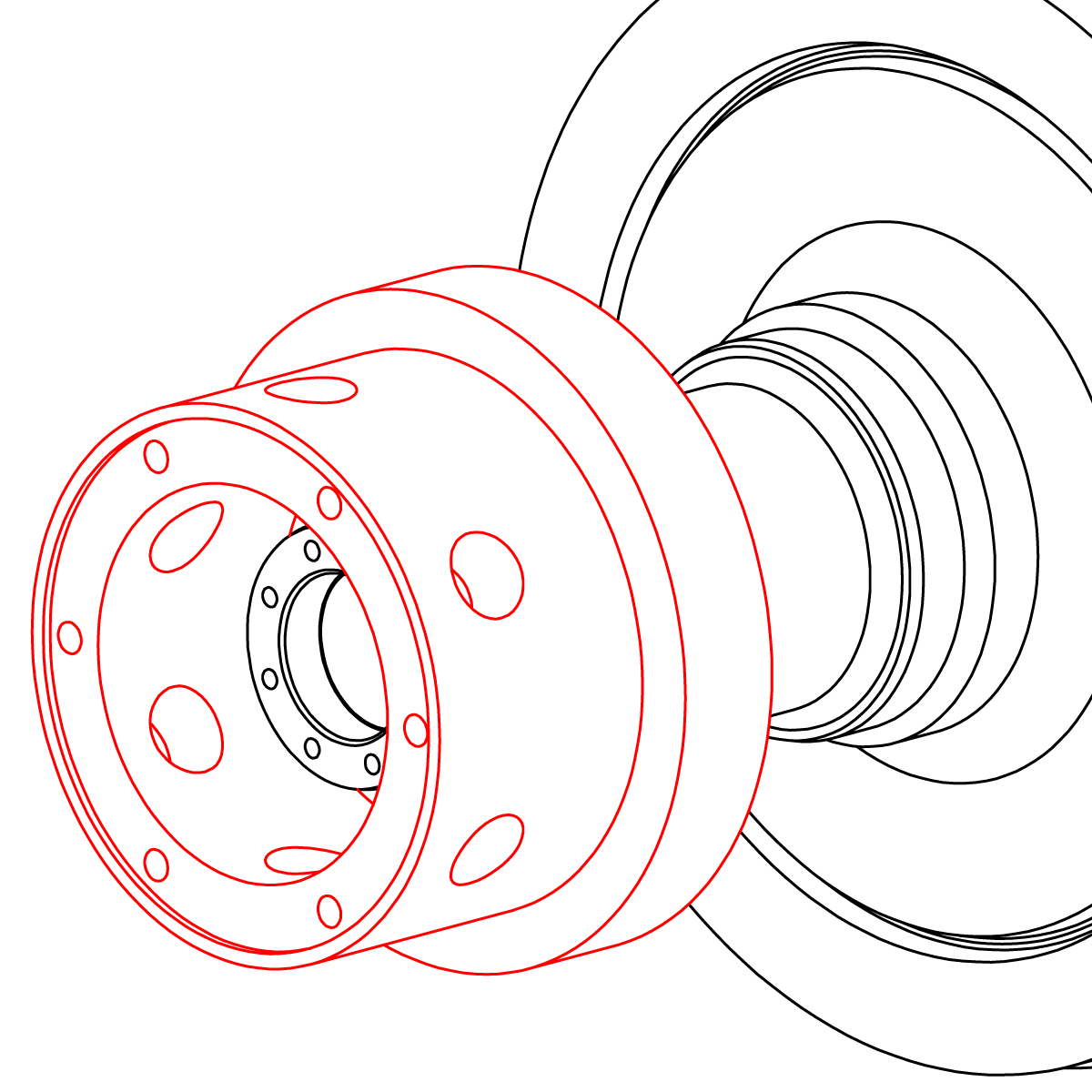
If the bracket is integrated into the bearing cover, follow the machine manufactures installation recommendations. The journal flange will need to be removed if its outer diameter is greater than the journal outer diameter.
If applicable, install the journal flange using the correct gasket and/or O-ring(s).
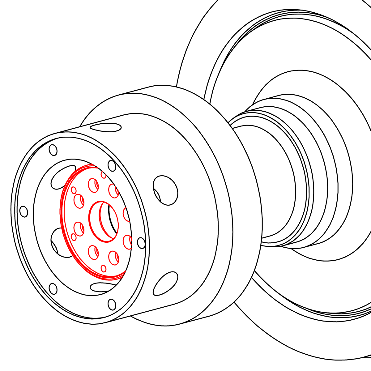
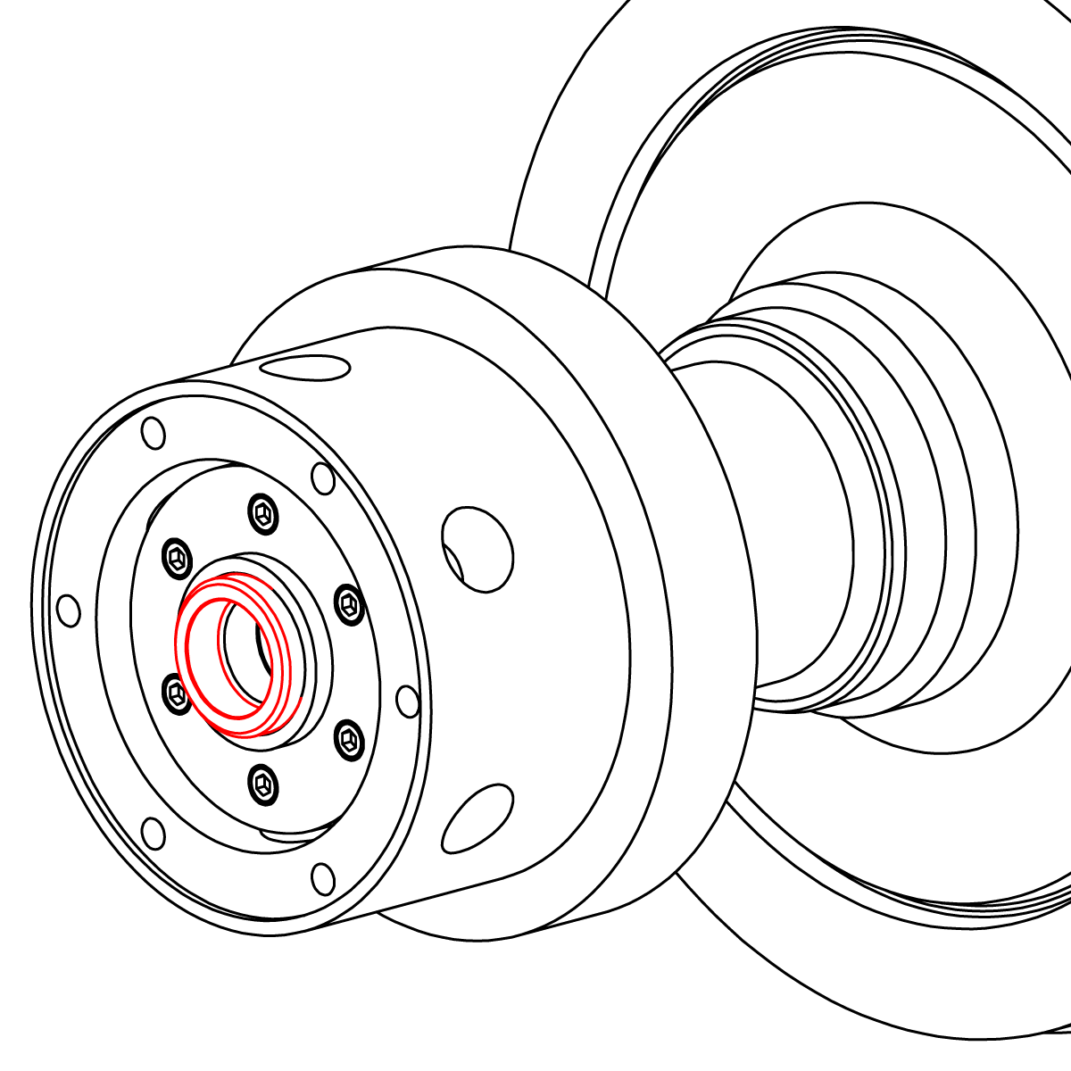
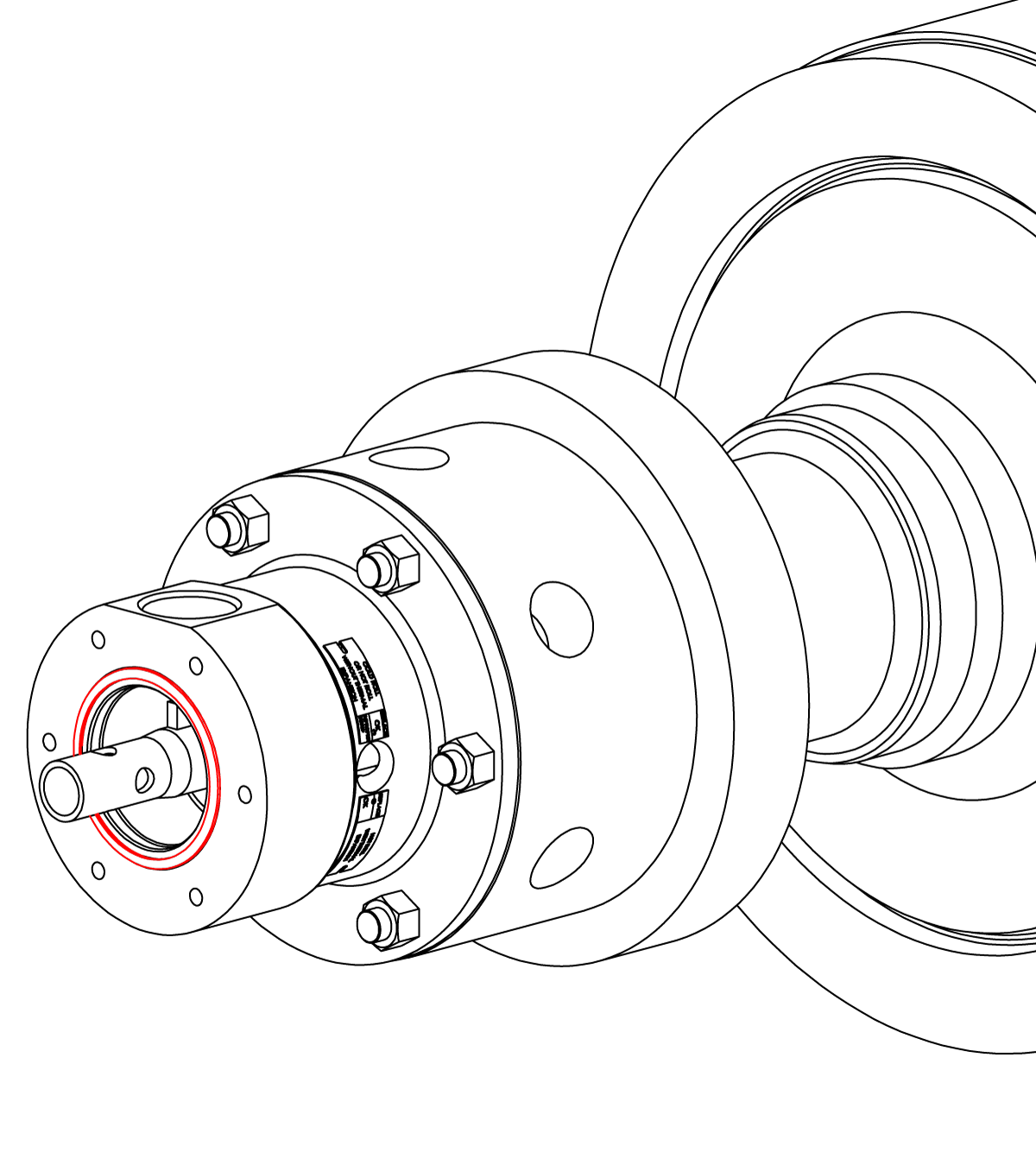
Install the wear plate using the applicable O-ring(s) and/or gasket.
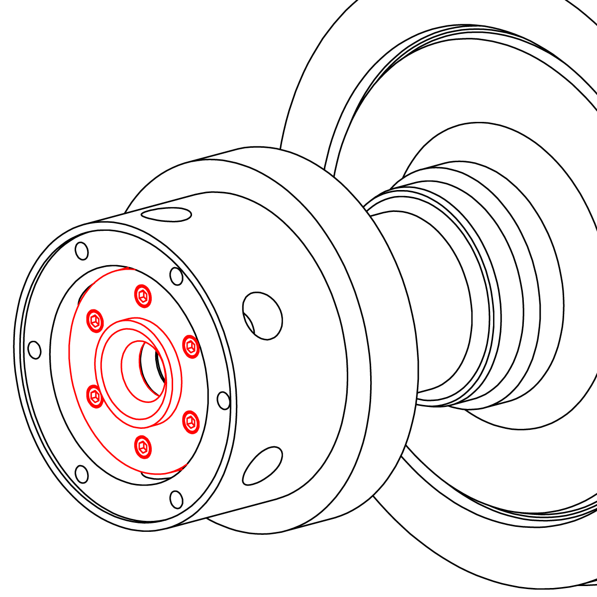
Place three equally spaced drops of seal ring installation fluid on the conical side of the seal ring. Install the seal ring.
Important: Make sure the seal ring is centered and does not fall off the wear plate.
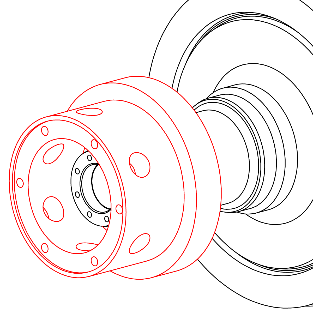
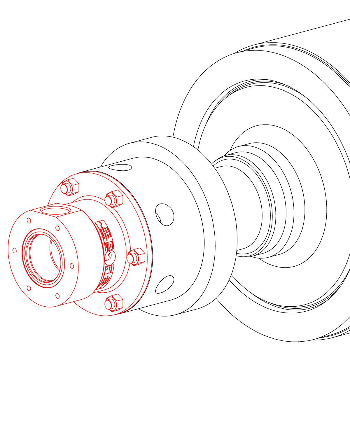
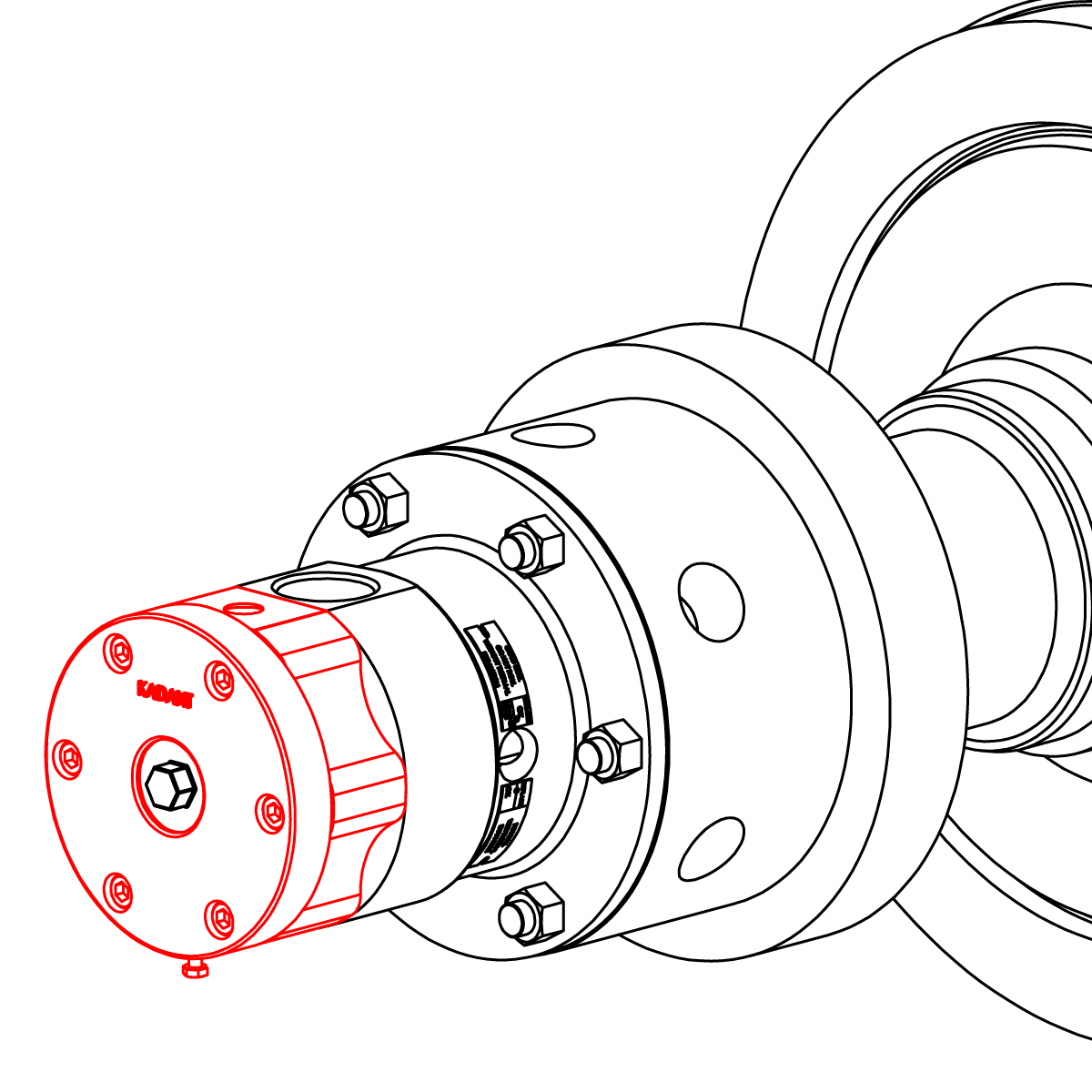
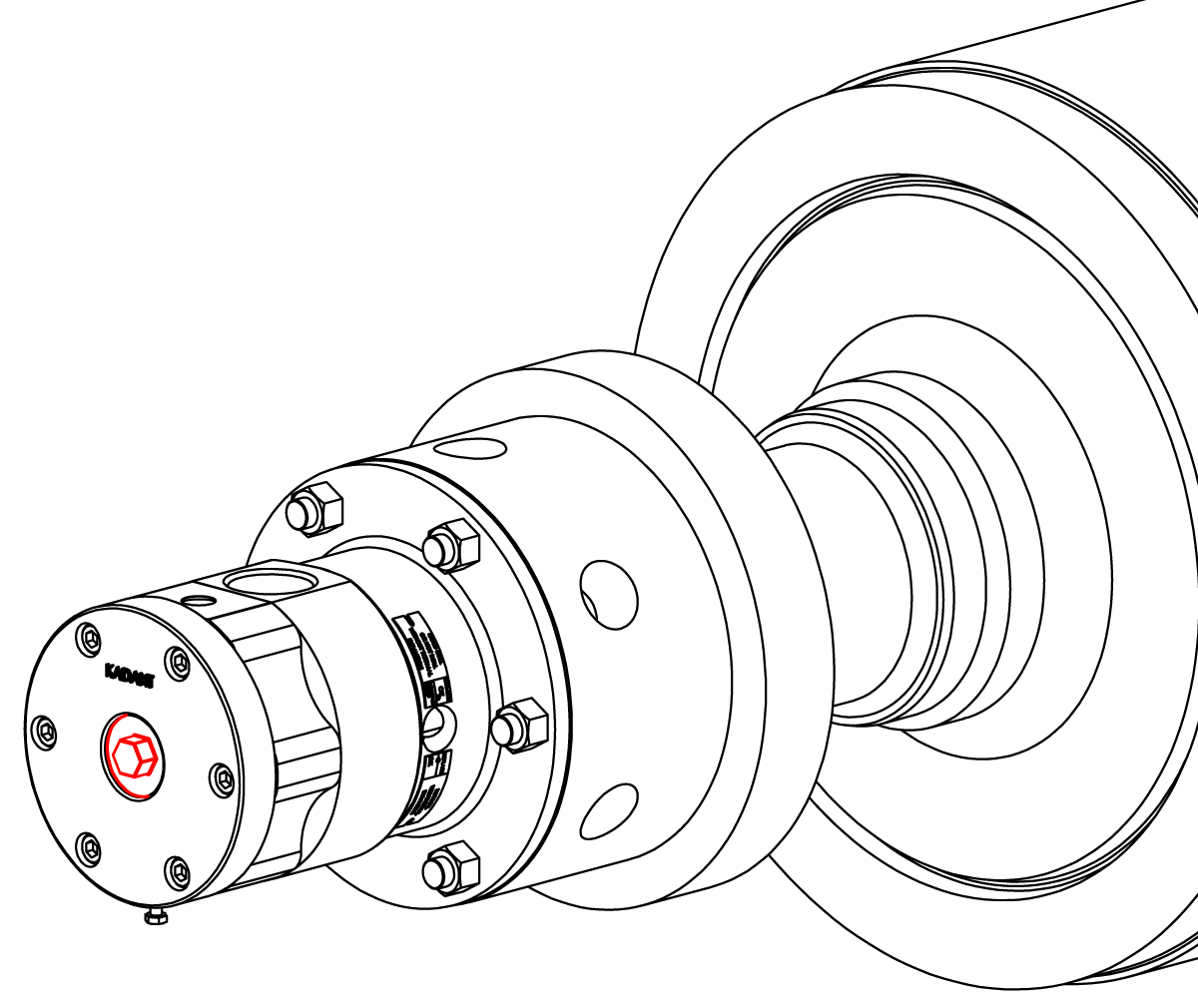
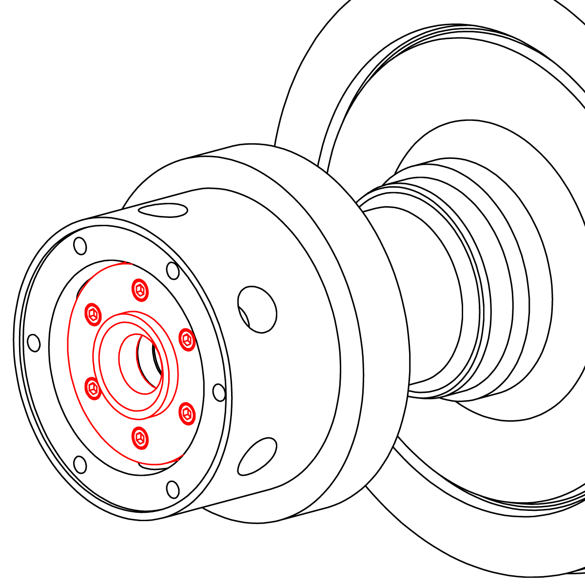
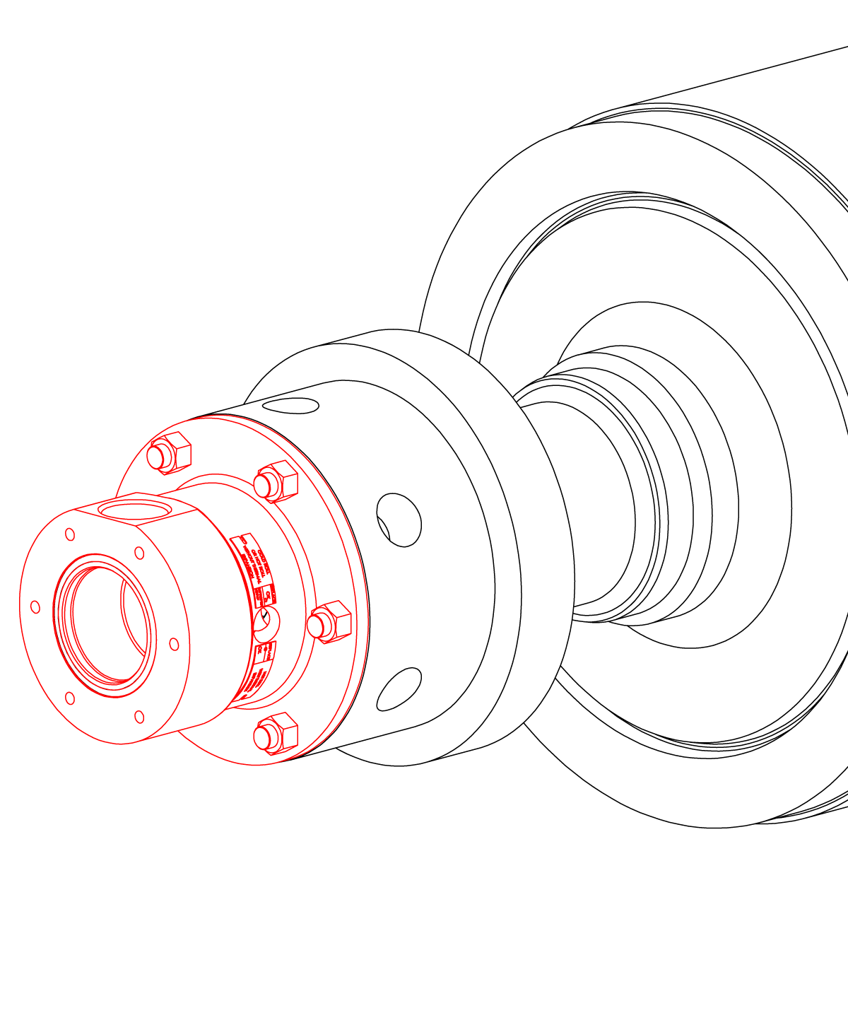
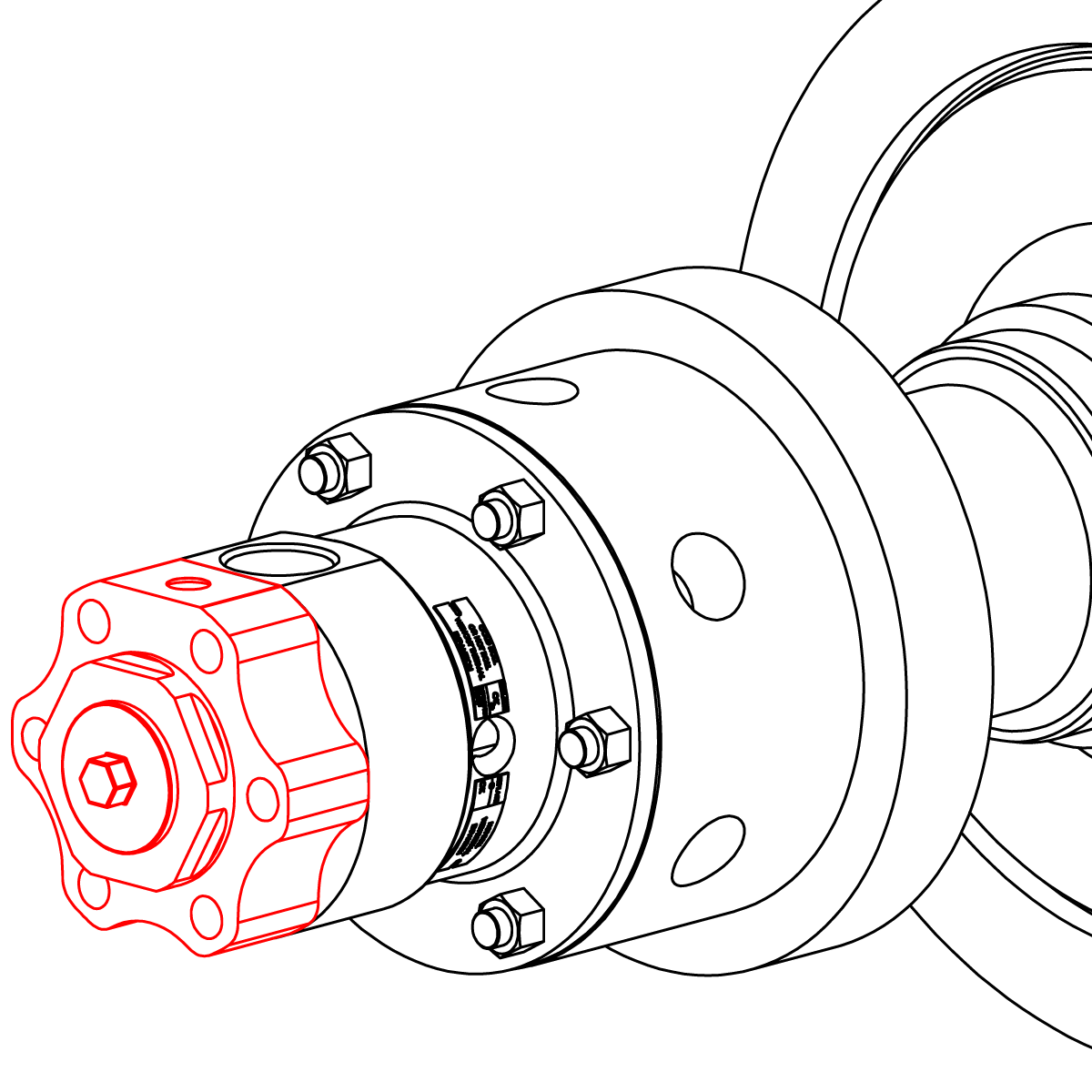
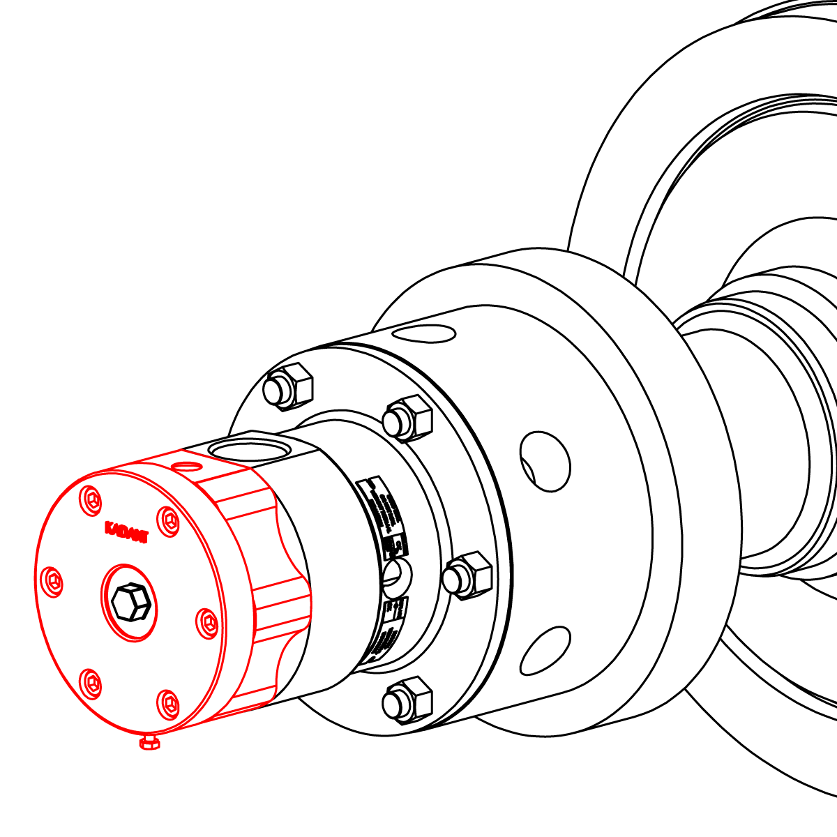
Install the body assembly to the bracket and secure with the provided fasteners (1A).
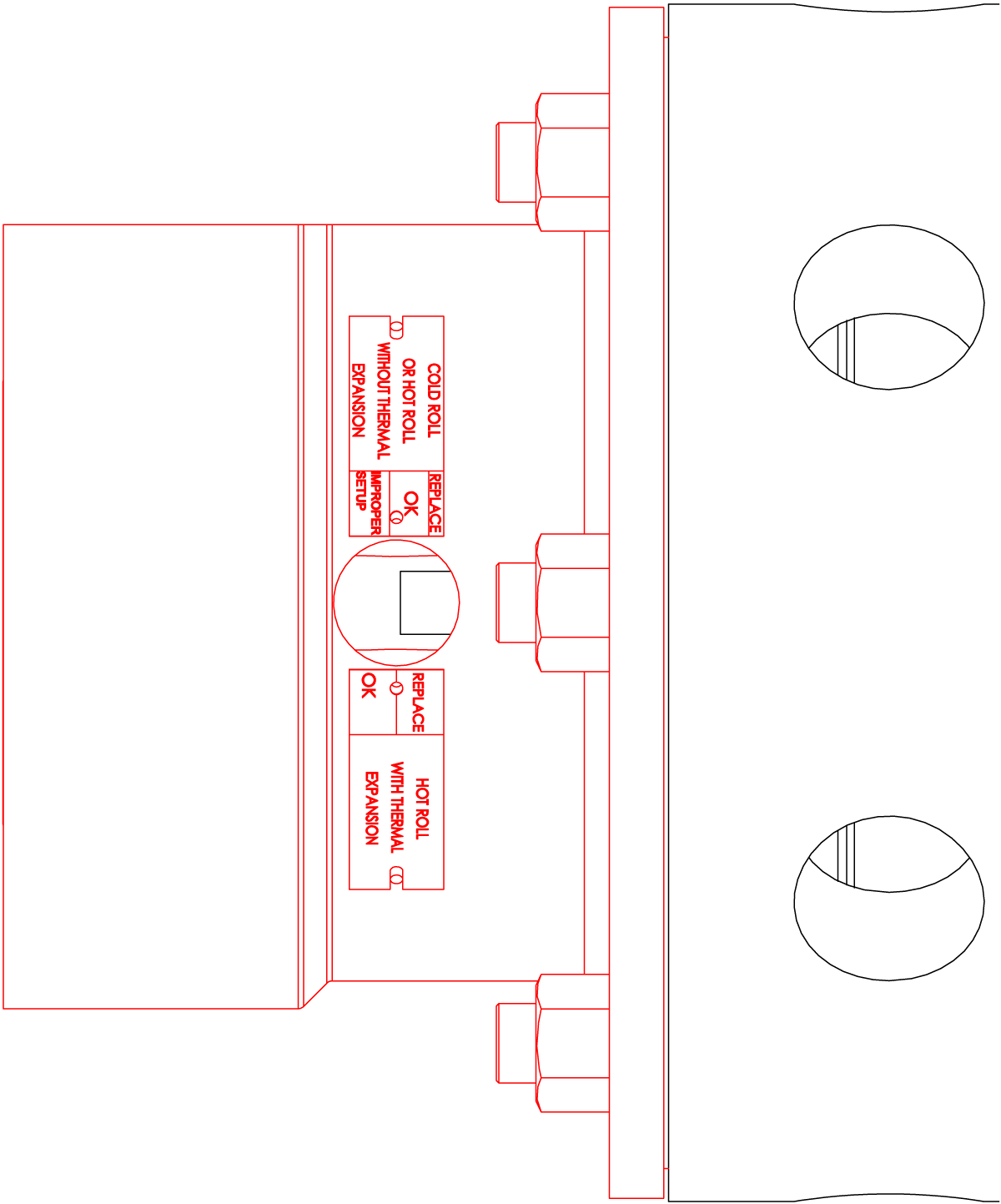
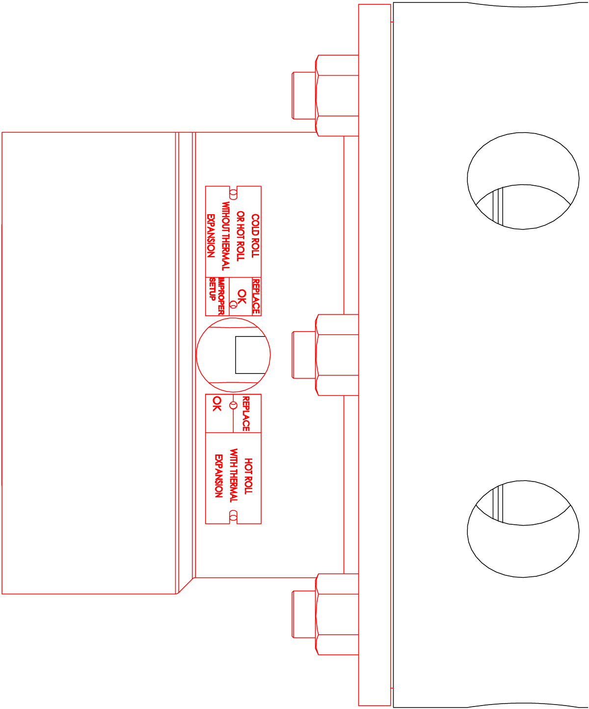
Important: Check the visual indicator to ensure proper set-up.
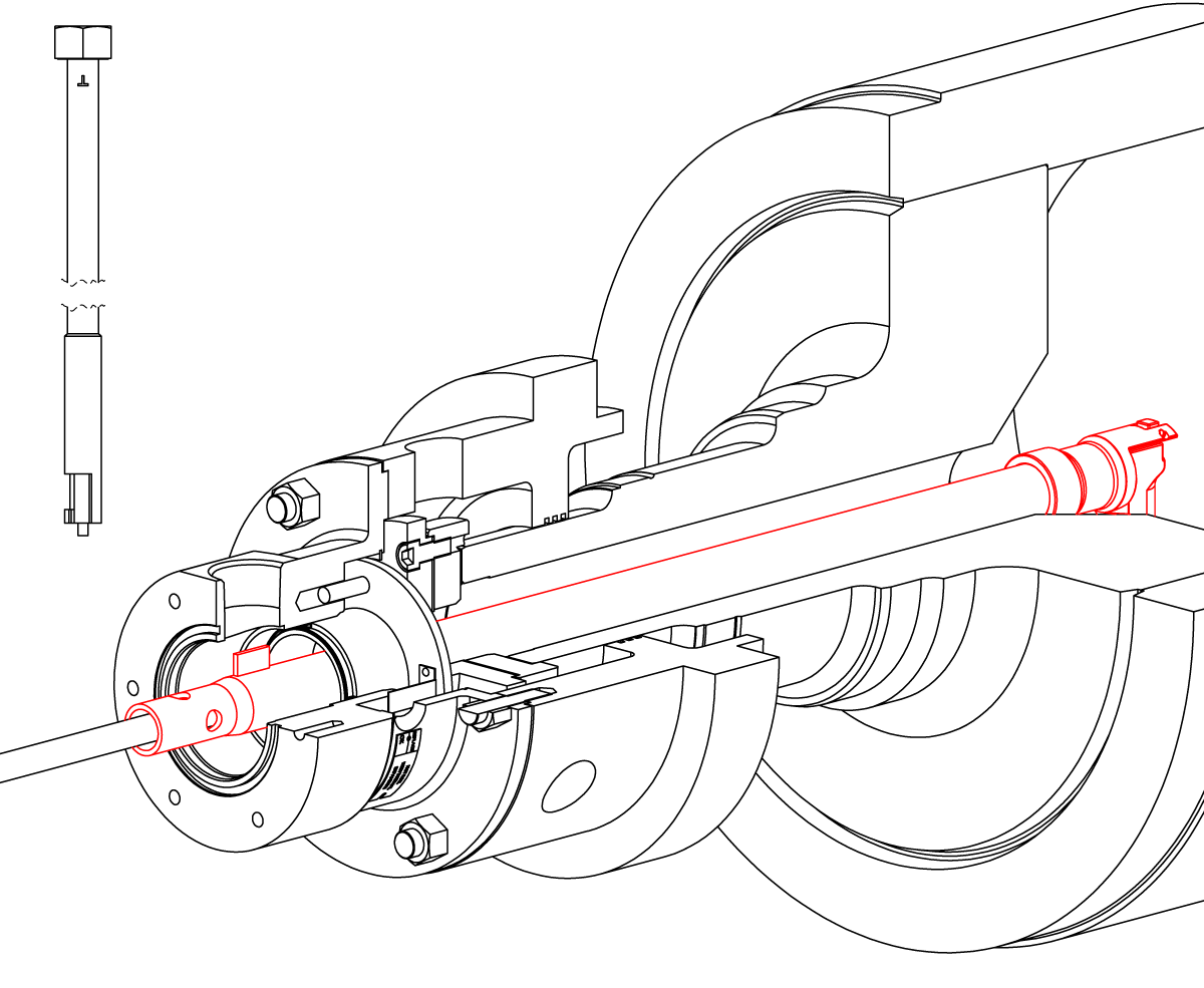
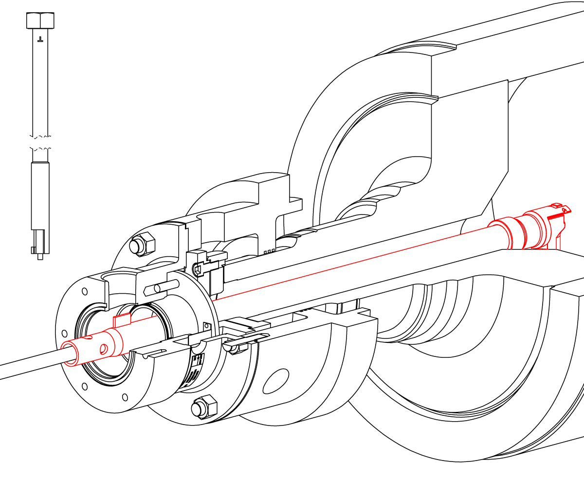
With the syphon straight, apply Loctite® 242 to the threaded insert. Insert the syphon into the journal and gently rotate the vertical leg to the six-o-clock position.
Insert the syphon handling tool until it contacts the insert. Turn the tool clockwise to engage the locking insert. Turn an additional two times to ensure engagement.
While applying pressure on the tool, rotate counterclockwise until the stamped "T" on the tool is facing up. Pull the tool back approximately 1" (25 mm). Push the tool forward while turning the tool clockwise. The insert will begin to thread into the vertical leg. Tighten the insert to 50 ft-lbs (68 Nm).
Tip: Pull the syphon toward you to confirm that the vertical leg is locked.
Apply anti-seize to the threads and tapered portion of the horizontal tube. Lubricate and install a cup seal (12 and 2E) in the body and head.
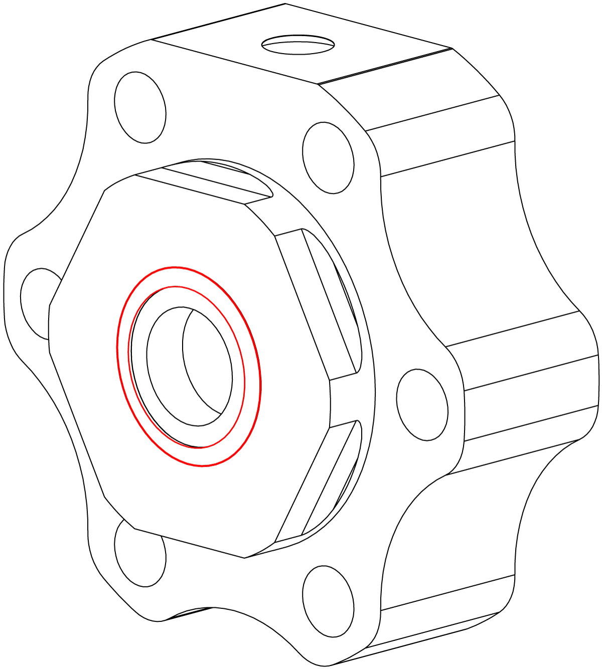
Position the head on the horizontal tube. Finger tighten the nut on the horizontal tube.
Important: Make sure that the key on the horizontal pipe is engaged with the keyway on the head.
Note: Orient the outlet connection in the desired position.
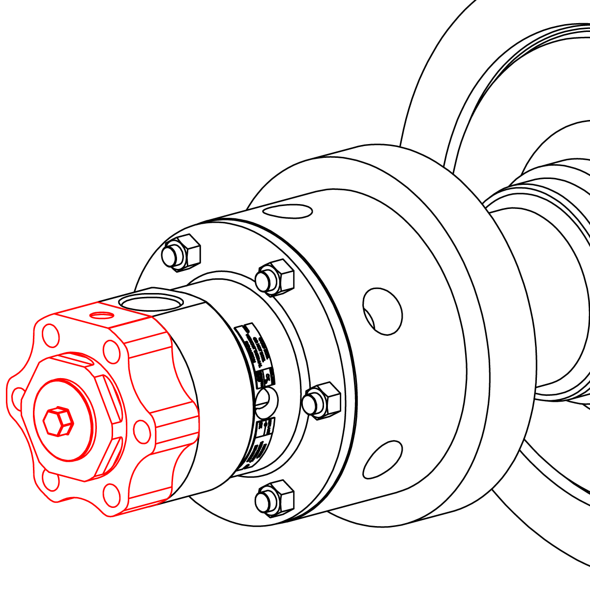
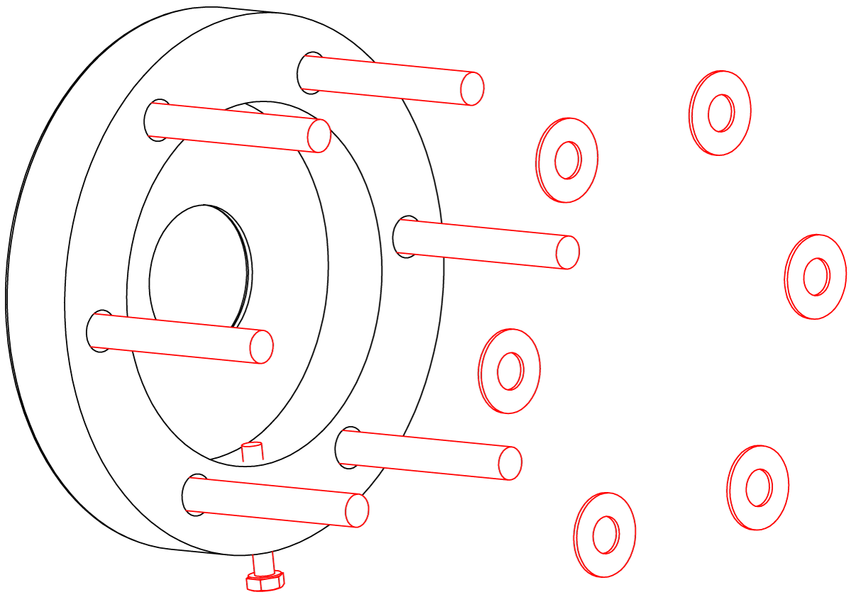
Turn the adjustment screw until it is below the ID of the retaining ring. Insert the cap screws (2A) into the retaining ring. Slide the spring washers (2B) over the cap screws with the convex side facing the retaining ring.
Install the retaining ring into the head. Fasten retaining ring and head to the body with cap screws. Torque 30 to 42 ft-lbs (41 to 57 Nm).
Important: Install the retaining ring and head so that they are centered on the body.
Torque the horizontal tube nut to 175 to 200 ft-lbs (237 to 271 Nm). Pipe the rotary joint.
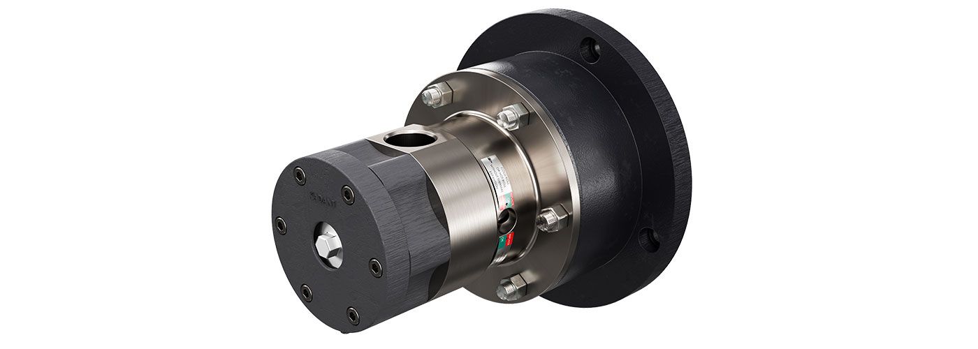
IS-9500CorrPro-12mm-Stationary-1

